METAL CASTING PROCESSES
INTRODUCTION
This chapter focuses on the major metal casting processes and their principles, advantages and limitation. Many parts and components are made by casting, including carburetors, frying pans, engine blocks, crankshafts, railroad-car wheels plumbing fixtures power tools, gun barrels and machine bases. Various casting processes have been developed over a long period of time, each with its own characteristics and application, to meet specific engineering and service requirements. In fact the first casting were made during the period of 4000-3000B.C, using stone and metal molds for castings copper.
Two trends currently are having a large impact on the casting industry. The first is continuing machanization and automation of the casting process, which has led to significant changes in the use of equipment and labour. Advanced machinery and automated process- control systems have replaced traditional methods of casting. Moreover, casting processes that especially lend themselves to advances in technology are developing significant economic advantages over other processes.
The second major trend affecting the casting industry is the increasing demand for high-quality casting with close tolerances. This demand is spurring the further development of casting processes that produce high quality castings. This chapter will emphasize the significance of these trends in the major casting processes.
Table 1: GENERAL CHARACTERISTICS OF CASTIN PROCESSES
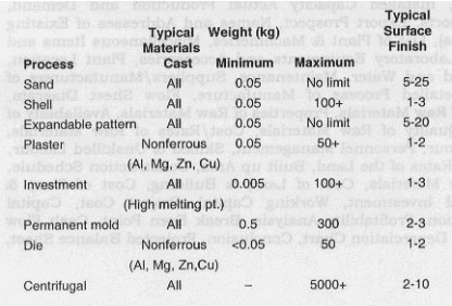
Note : These ratings are only general; significant variations can occur, depending on the methods used.
This chapter is organized around the major classifications of casting practices. These classifications are related to mold materials, molding processes and methods of feeding the mold with the molten metal. The two major categories are expendable-mold and permanent-mold casting.
Expendable molds are made of sand, plaster, ceramics and similar materials which are generally mixed with various bindes or bonding agents. As described in Chapter 8, these materiasl are refractories, that is ,they have the capability to withstand the high temperatures of molten metals. After the casting has solidified, the molds in these processes are broken up to remove the casting.
Permanent modls, as the name implies, are used repeatedly and are designed in such a way that the casting can be easily removed and the mold used for the next casting. These molds are made of metals that maintain their strength at high temperatures and thus can be used,repeatedly. Because metal molds are better heat conductors than expendable molds the solidifying casting is subjected to a higher rate of cooling, which in turn affects the microstructure and grain size within the casting.
Composite molds are made of two or more different materials, such as sand, graphite, and metal, combining the advantages of each material. They are used in various casting processes to improve mold strength, cooling rates, and overall economics of the process.
Sand Casting
The traditional method of casting metals is in sand molds and has been used for millenia. Simply stated, sand casting consists of placing a pattern (having the shape of the desired casting) in sand to make an imprint, incorporating a gating system, filling the resulting cavity with molten metal, allowing the metal to cool until it solidifies, breaking away the sand mold, and removing the casting. Although the origins of sand casting date to ancient times, It is still the most prevalent form of casting. In the United States alone, about 15 million tons of metal are cast by this method each year. Typical parts made by sand casting are machine- tool bases, engine blocks, cylinder heads, and pump housings.
1 Sands.
Most sand casting operations use silica sand (SiO2). Sand is the product of the disintegration of rocks over extremely long periods of time. It is inexpensive and is suitable as mold material because of its resistance of high temperatures, There are two general types of sand: naturally bonded (bank sands) and synthetic (lake sands). Because its composition can be controlled more accurately, synthetic sand is preferred by most foundries. Several factors are important in the selection of sand for molds. Sand having fine, round grains can be closely packed and forms a smooth mold surface. Good permeability of molds and cores allows gases and steam evolved during casting to escape easily. The mold should have good collapsibility (the casting shrinks while cooling) to avoid defects in the casting, such as hot tearing and cracking.
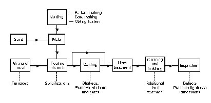
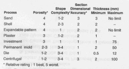
Fig. 1 Outline of production steps in a typical sand casting operation.
The selection of sand involves certain tradeoffs with respect to properties. For example, fine-grained sand enhances mold strength, but the fine grains also lower mold permeability. Sand is typically conditioned before use. Mulling machine are used to uniformly mull (mix thoroughly) sand with additives. Clay (bentonite) is used as a cohesives agent to bond sand particles, giving the sand strength. Zircon (ZrSiO4)Olivine (Mg2SiO4) and iron silicate (Fe2SiO4) sands are often used in steel foundries for their low thermal expansion. Chromite (FeCr2O4) is used for its high heat transfer property.
Types of sand molds.
Sand molds are characterized by the types of sand that comprise them and by the method used to produce them. There are Three basic of sand molds: green-sand, cold-box, and no-bake molds.
The most common mold material is green molding sand. The term green refers to the fact that the sand in the mold is moist or damp while the metal is being poured into it. Green molding sand is a mixture of sand, clay, and water. Green-sand molding is the least expensive method of making molds.
In the skin- dried method, the mold surfaces are dried, either by storing the mold in air or drying it with torches. Skin-dried molds are generally used for large castings because of their higher strength. Sand molds are also oven dried (baked) prior to receiving the molten metal. They are stronger than green-sand molds and impart better dimensional accuracy and surface finish to the casting. However, distortion of the mold is greater, the castings are more susceptible to hot tearing because of the lower collapsibility of the mold, and the production rate is slower because of the drying time required.
In the cold-box mold process, various organic and inorgainc binder are blended into the sand to bond the grains chemically for greater strength. These molds are dimensionally more accurate than green- sand molds but are more expensive.
In the no- bake mold process, a synthetic liquid resin is mixed with the sand, and the mixture hardens at room temperature. Because bonding of the mold in this and the cold-box process takes place without heat, they are called cold setting processes.
Major components of sand molds, as shown in Fig. 2 are:
- The mold itself, which is supported by a flask. Two-piece molds consist of a cope on top and a drag on the bottom. The seam between them is the parting line. When more than two pieces are used, the additional parts are called cheeks.
- A pouring basin or pouring cup, into which the molten is poured.
- A sprue through which the molten metal flows downward.
- The runner system, which has channels that carry the molten metal from the sprue to the mold cavity. Gates are the inlets into the mold cavity.
- Risers, which supply additional metal to the casting as it shrinks during solidification. Figure 2 shows two different types of risers: a blind riser and an open riser.
- Cores, which are inserts made from sand. They are placed in the mold to form hollow regions or otherwise define the interior surface of the casting. Cores are also used on the outside of the casting to form feature such as lettering on the side of a casting or deep external pockets.
- Vents, which are placed in molds to carry off gases produced when the molten metal comes into contact with the sand in the molds and core. They also exhaust air from the mold cavity as the molten metal flows into the mold.
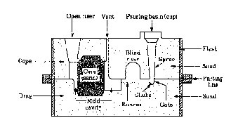
Fig. 2. Schematic illustration of a sand mold showing various features
3 Patterns
Patterns are used to mold the sand mixture into the shape of the casting. They may be made of wood, plastic, or metal. The selection of a pattern material depends on the size and shape of the casting, the dimensional accuracy and the quantity of casting required, and the molding process to be used. Because patterns are used repeatedly to make molds, the strength and durability of the material selected for patterns must reflect the number of casting that the mold will produce. They may be, made of a combination of materials to reduce wear in critical regions. Patterns are usually coated with a parting agent to facilitate their removal from the molds.
Table 2 CHARACTERISTICS OF PATTERNS MATERIALS
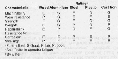
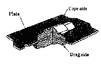
Fig. 3 A typical metal plate pattern used in sand casting.
Patterns can be designed with a variety of features to fit application an economic requirement . One piece patterns, also called loose or solid patterns, are generally used for simpler shapes and low-quantity production. They are generally made of wood and are inexpensive. Split patterns two-piece patterns made so that each part forms portion of the cavity for the casting. In this way casting having complicated shapes can be produced. Match-plate patterns are a popular type of mounted patterns in which two piece patterns are constructed by securing each half of one or more split patterns to the opposite sides of a single plate. In such constructions, the gating system can be mounted on the drag side of the pattern. This type of pattern is used most often in conjunction with molding machines and large production runs to produce smaller castings.
An important recent development is the application of rapid prototyping to mold and pattern making. In investment castings for example, wax patterns can now be replaced with accurate resin patterns made directly by rapid prototyping (using CAD data an without the need for dies), at a fraction of the time and cost of dies for making wax patterns. There are several technologies using computer-aided design and manufacturing by which these parts and related components can be made rapidly, reducing produciton time and cost.
Pattern design is a crucial aspect of the total casting operation. The design should provide for metal shrinkage, ease of removal from the sand mold by means of taper or draft and proper metal flow in the mold cavity.
4. Cores
For casting with internal cavities or passages, such as in an automotive engine block or a valve body, cores are utilized. Cores are ed placed in the mold cavity before casting to form the interior surface of the casting and are removed from the finished part during shakeout an further processing. Like molds, cores must possess strength permeability, ability to withstand heat, and collapsibility. Therefore cores are made of sand aggregates.
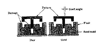
Fig. 4 Taper on patterns for ease of removal from the sand mold.
The core is anchored by core prints. These are recesses that are added to the pattern to support the core and to provide vents for the escape of gases. A common problem with cores is that for certain casting requirements, as in the case where a recess is required, they may lack sufficient structural support in the cavity. To keep the core from shifting, metal supports, known as chaplets, may be used to anchor the core in place.
Cores are generally made in a manner similar to that used in making molds, and the majority are made with shell, no-bake, or cold-box processes. Cores are formed in core boxes, which are used much like patterns are used to form sand molds. The sand can be packed into the boxes with sweeps or blown into the box by compressed air from core blowesr. Core blowers have the advantages of producing cores and operating at a very high production rate.
5 Sand-molding machines.
The oldest known method of moldings, which is still used for simple castings is to compact the sand by hand hammering or ramming it around, the pattern. For most operations, however, the sand mixture is compacted around the pattern by molding machines. These machines aliminate arduous labour. Offer high quality casting by improving the application and distribution of forces, manipulate the mold in a carefully controlled fashion, and increase the rate of production.
Fig. 5. Wxamples of sand cores supported by core prints.
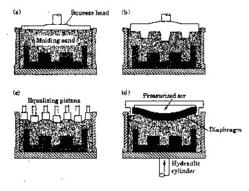
Fig. 6. Various designs of squeeze heads for mold making : (a) conventional flat head;(b) profile head; (c) equalizing squeeze pistons; and (d) flexible diaphragm
Mechanization of the molding process can be further assisted by jolting the assembly. The flask, molding sand, and pattern are placed on a pattern plate mounted on an anvil, and jolted upward by air pressure at rapid intervals. The incertial forces compact the sand around the pattern. Jolting produces the highest compaction atr the horizontal parting line, whereas in squeizing, compaction is highest at the squeezing head. Thus more uniform compaction can be obtained by combining them.
In vertical flaskless molding, the halves of the pattern form a vertical chamber wall against which sand is blown and compacted. Then the mold halves are packed horizontally, with the parting line oriented vertically and moved along a pouring conveyor. This operation is simple and eliminates the need to handle flasks, making potential production rates very high, particularly when other aspects of the operation, such as coring and pouring, are automated.
Sandslingers fill the flask uniformly with sand under a stream of high pressure. They are used to fill large flasks and are typically operated by machine. An impeller in the machine throws sand from its blades or cups at such high speeds that the machine not only places the sand but also rams it appropriately.
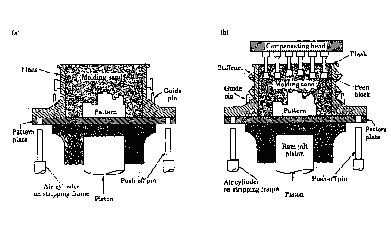
Fig. 7 (a) Schematic illustration of a jolt type mold making machine (b) Schematic illustration of a mold making machine which combines joltings and squeezing.
In impact molding, the sand is compacted by controlled explosion or instantaneous release of compressed gases. This method produces molds with uniform strength and good permeability.
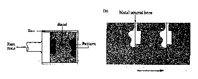
Fig. 8 Vertical flaskless molding. (a) Sand is squeezed between two halves of the pattern (b) Assembled molds pass along an assembly line for pouring.
In vacuum molding, also known as the "V' process, the pattern is covered tightly by a thin sheet of plastic. A flask is placed over the coated pattern and is filled with dry binderless sand. A second sheet of plastic is placed on top of the esand, and a vacuum action harders the sand so that the pattern can be withdrawn. Both halves of the mold are made this way and then assembled. During pouring, the mold remains under a vacuum but the casting cavity does not. When the metal has solidified, the vacuum is turned off and the sand falls away, releasing the casting. Vacuum molding produces castings having very good detail and accuracy. It is especially well suited for large, relatively flat castings.
6. The sand-casting operation
After the mold has been shaped and the cores have been placed in position, the two halves (cope and drag) are closed, clamped, and weighted down. They are weighted to prevent the separation of the mold sections under the pressure exerted when the molten metal is poured into the mold cavity.
The design of the gating system is important for proper delivery of the molten metal into the mold cavity. Turbulence must be minimized, air and gases must be allowed to escape by such means as vents, and proper temperature gradients must be established and maintained to minimize shrinkage and porosity. The design of risers is also important in order to supply the necessary molten metal during solidification of the casting. The pouring basin may also serve as a riser. A complete sequence of operations in sand casting is shown in Fig.9.
After solidification, the casting is shaken out of its mold, and the sand and oxide layers adhering to the casting are removed by vibration (using a shaker) or by sand blasting. Ferrous castings are also cleaned by blasting with steel shot (shot blasting) or grit. The riser and gates are cut off by oxyfuel-gas cutting, sawing, shearing, and abrasive wheels, or they are trimmed in dies. Gates and risers on steel casting are also removed with air carbon-arc or powder injection torches. Castings may be cleaned by electrochemical means or by pickling with chemicals to remove surface oxides.
The surface of castings is important in subsequent machining operations, because machinability can be adversely affected if the casting are not cleaned properly and sand particles remain on the surface. If regions of the casting have not formed properly or have formed incompletely, the defects may be repaired by welding by filling them with weld metal. Sand-mold castings generally have rough, grainy surfaces, although that depends on the quality of the mold and the materials used.
Depending on the metal used, the casting may subsequently be heat treated to improve certain properties neeeded for its intended service use; these processes are particularly important for steel castings. Finishing operations may involve straightening or forging with dies to obtain final dimensions and machining. Minor surface imperfections may also be filled with a metal-filled epoxy, especially for cast-iron castings because they are difficult to weld. Inspection is an important final step and is carried out to ensure that the casting meets all design and quality-control requirements.
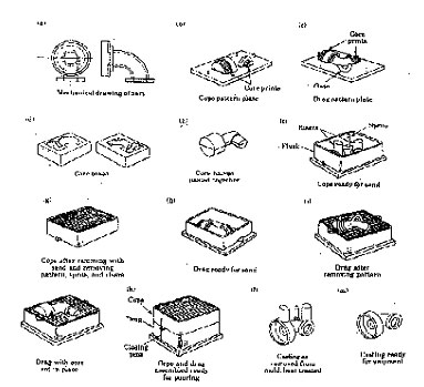
Fig. 9 Schematic illustration of the sequence of operations for sand casting. Source: Steel Founders' Society of America. (a) A mechanical drawing of the part is used to generate a design for the pattern. Considerations such as part shrink age and draft must be built into the drawing. (b-c) Patterns have been mounted on plates equipped with pins for alignment. Note the presence of core prints designed to hold the core in place. (d-e) Core boxes produce core halves, which are pasted together. The cores will be used to produce the hollow area of the part shown in(a). (f) The cope half of the mold is assembled by taking the cope pattern plate, securing it to the flask through aligning pins, and attaching inserts to form the sprue and risers. (g) The flask is rammed with sand and the plate and inserts are removed. (h) The drag half is produced in a similar manner, with the pattern inserted. A bottom board is placed below the drag and aligned with pins. The pattern, flask and bottom board are inverted, and the pattern is withdrawn, leaving the appropriate imprint. (j) The core is set in place within the drag cavity. (k) The mold is closed by placing the cope on the top of the drag and securing the assembly with pins. The flasks are then subjected to pressure to counteract buoyant forces in the liquid, which might lift the cope. (l) After the metal solidifies, the casting is removed from the mold. (m) The sprue and risers are cut off and recycled, and the casting is cleaned, inspected, and heat treated (when necessary).
Almost all commercially used metals can be sand cast. The surface finish obtained is largely a function of the materials used in making the mold. Dimensional accuracy is not as good as that of other processes. However, intricate shapes can be cast by this process, such as cast iron engine blocks and very large propellers for ocean linear. Sand casting can be economical for relatively small production runs, and equipment costs are generally low. The characteristics of sand casting and other casting processes are given in Table.1
Shell-Mold Casting
Shell-mold casting was first developed in the 1940s and has grown significantly because it can produce many types of castings with close tolerances and good surface finishes at a low cost. In this process, a mounted pattern made of a ferrous metal or aluminium is heated to 175- 370°C ( 350- 700° F), coated with a parting agent such as silicone, and clamped to a box or chamber containing a fine sand containing 2.5 to 4.0 percent thermosetting resin binder such as phenol-formaldehyde, which coats the sand particles. The box is either rotated upside down or sand mixture is blown over the pattern, allowing it to coat the pattern.
The assembly is then placed in an oven for a short period of time to complete the curing of the resin. The oven in most shell-molding machine is a metal box with gas fired burners that swings over the shell mold to cure it. The shell hardens around the pattern and is removed from the pattern using built-in ejector pins. Two half-shells are made in this manner and are bonded or clamped together in preparation for pouring.
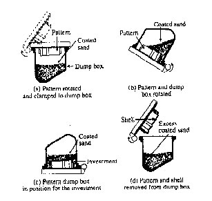
Fig. 10 A common method of making shell molds. Called dump box technique, the limitations are the formation of the voids in the shell and peelback (when sections of the shell fall off as the pattern is raised).
The thickness of the shell can be accurately determined by controlling the time that the pattern is in contact with the mold. In this way, the shell can be formed with the required strength and rigidity to hold the weight of the molten liquid. The shells are light and thin, usually 5-10 mm (0.2-0.4 in) and consequently their thermal characteristics are different from those for thicker molds. Shell sand has a much lower permeability than sand used green-sand molding, because a sand of much smaller grain size is used for shell molding. The decomposition of the shell sand binder also produces a high volume of gas. Unless the molds are properly vented, trapped air and gas can cause serious problems in shell-molding of ferrous castings.
Shell-molds are generally poured with the parting line horizontal and may also be supported by sand. The walls of the mold are relatively smooth, offering low resistance to flow of the molten metal and producing casting with sharper corners, thinner sections, and smaller projections than are possible in green sand molds. With the use of multiple gating systems, several castings can be made in a single mold. Nearly any metal suited for sand casting may be cast by the shell-mold process.
Shell mold casting may be more economical than other casting proceses, depending on various factors. The cost of the resin binders is offset somewhat by the fact that only 5 percent as much sand is used, compared to sand casting. The relatively high cost of metal patterns becomes a smaller factor as the size of production runs increases. The high quality of the finished casting can significantly reduce cleaning machining, and other finishing costs. Complex shapes can be produced with less labour, and the process can be automated fairly easily. Shell molding applications include small mechanical parts requiring high precision, such as gear housings, cylinder heads and connecting rods. Shell-molding is also widely used in producing high-precision molding cores.
1. Composite molds
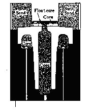
Composite molds are made of two or more different materials and are used in shell molding and other casting processes. They are generally employed in casting complex shapes, such as impellers for turbines. Examples of composite molds are shown in Figs.11 and12 . Molding materials commonly used are shells., plaster, sand with binder, metal, and graphite. Composite molds may also include cores and chillls to control the rate of solidification in critical areas of castings. Composite molds increase the strength of the mold, improve the dimensional accuracy and surface finish of castings, and may help reduce overall costs and processing time.
Graphite
Fig. 11 Schematic illustration of a semipermanent Composite mold.
2 Sodium silicate process
The mold material in the sodium silicate process is a mixture of sand and 1.5 to 6 percent sodium (waterglass) as the binder for sand. This mixture is packed around the pattern and hardened by blowing carbon dioxide (CO2) gas through it. This process, also known silicate- bonded sand or the carbon-dioxide process, was first used in the 1950s and has been developed further, for example, by using various other chemicals for binders. Cores made by this process reduce the tendency to tear because of their compliance at elevated temperatures.
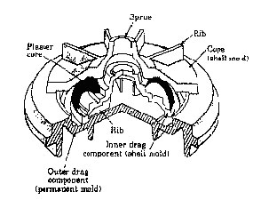
Fig. 12 A Composite mold used in casting an aluminium alloy torque converter. This part was previously cast in an all-plaster mold.
3. Rammed graphite molding
Rammed graphite, instead of sand, is used to make molds for casting reactive metals, such as titanium and zirconium. Sand cannot be used because these metals react vigorously with silica. The molds are packed rather like sand molds then air dried, baked at 175°C (350°F) fired at 870°C( 1600°F), then stored under controlled humidity and temperature. The casting procedures are similar to those for sand molds.
EXPANDABLE PATTERN CASTING (LOST FOAM)
The expandable pattern casting process uses a polystyrene pattern, which evaporates upon contact with molten metal to form a cavity for the casting. The process is also known as evaporative-pattern or lost-pattern casting, and under the trade name Full-Mold process. It was formerly known as the expanded polystyrene process, and has become one of the more important casting processes for ferrous and nonferrous metals, particularly for the automotive industry.
First, raw expandable polystyrene (EPS) beads, containing 5 to 8 percent pentane (a volatile hydrocarbon) are placed in a preheated die, usually made of aluminium. The polystyrene expands and takes the shape of the die cavity. Additional heat is applied to fuse and bond the beads together. The die is then colled and opened, and the polystyrene pattern is removed. Complex pattern may also be made by bonding various individual pattern sections using hot-melt adhesive.
The pattern is then coated with a water-base refractory slurry, dried, and placed in a flask. The flask in filled with loose fine sand, which surrounds and supports the pattern. The sand may be dried or mixed with bonding agents to give it additional strength. The sand is periodically compacted by various means. Then, without removing the polystyrene pattern, the molten metal is poured into the mold. This action immediately vapourizes the pattern (an ablation process) and fills the mold cavity, completely replacing the space previously occupied by the polystyrene pattern. The heat degrades (depolymerizes) the polystyrene and the degradation products are vented into the surrounding sand.
The flow velocity in the mold depends on the rate of degradation of the polymer. Studies have shown that the flow of the molten metal is basically laminar, with Reynolds numbers in the range of 400 to 3000. The velocity of the molten-metal at the metal polymer patterns front is estimated to be in the range of 0.1- 1.0 m/s. The velocity can be controlled by producing pattern with cavities or hollow sections, thus the velocity will increase as the molten crosses these hollow region, similar to pouring in an empty cavity as is done in sand casting. Furthermore, because the polymer requires considerable energy to degrade, large thermal gradients are present at the metal-polymer interface; in other words, the molten metal cools faster than it would if it were poured into a cavity. Consequently, fluidity is less than in sand casting. This has important effects on the microstructure throughout the casting and also leads to directional solidification of the metal.
The evaporative-pattern process has a number of advantages over other casting methods:
- It is a relatively simple process because there are no parting lines, cores, or riser systems; hence it has design flexibility.
- Inexpensive flasks are sufficient for the process.
- Polystyrene is inexpensive and can be easily processed into patterns having very complex shapes, various sizes, and fine surface detail.
- The casting requires minimum finishing and cleaning operation.
- The process is economical for long production runs. A major factor is the cost to produce the die for expanding the polystrene beads to make the pattern.
- The process can be automated.
Typical applications for this process are cylinder heads, crankshafts brake components and manifolds for automobiles, and machine bases. The aluminium engine blocks and other component of the General Motors Saturn automobile are made by this process. Recent developments include the use of polymethylmethacrylate (PMMA) and polyalkylene carbonate as patterns material for ferrous castigns. In a modification of the evaporative pattern process, a polystrene pattern is surrounded by a ceramic shell (Replicast C-S process). The pattern is burned out prior to pouring the molten metal into the mold. Its principal advantages over investment casting (with its wax patterns) is that carbon pickup into the metal entirely avoided.
New developments in evaporative pattern casting include production of metal matrix composites. During the process of molding the polymer pattern,. it is embedded throughout with fibers or particles, which then become an integral part of the casting. Further studies include modification and grain refinement of the casting by the use of grain refiners and modifier master alloys within the pattern while it is being molded.
Plaster Mold casting
In the plaster mold casting process, the mold is made of plaster of pairs (gypsum, or calcium sulfate), with the addition talc and silica flour to improve strength and control the time required for the plaster to set. These components are mixed with water, and the resulting slurry is poured over the pattern. After the plaster sets, usually within 15 minutes, the pattern is removed and the mold is dried at 120-260.C (250-500°F) to remove the moisture. Higher drying temperature may be used depending on the type of plaster. The mold halves are then assembled to form the mold cavity and preheated to about 120°C (250°F) The molten metal is then poured into the mold.
Because plaster molds have very low permeability, gases evolved during solidification of the metal cannot escape. Consequently, the molten metal is poured either in a vacuum or under pressure. Plaster-mold permeability can be increased substantially by the Antioch Process: The molds are dehydrated in an autoclave (pressurized oven) for 6-12 hours, then rehydrated in air for 14 hours. Another method of increasing permeability is to use foamed plaster, containing trapped air bubbles.
Patterns for plaster molding are generally made of aluminium alloys, thermosetting plastics, brass, or zinc alloy. Wood pattern are not suitable for making a large number of molds, because the patterns are repeatedly subjected to the water-based plaster slurry. Since, there is a limit to the maximum temperature that the plaster mold can withstand, generally about 1200°C (2200°F) plaster mold casting is used only for aluminium magnesium, zinc and some copper-base alloys. The castings have fine details with good surface finish. Because plaster molds have lower thermal conductivity than others, the castings cool slowly, and more uniform grain structure is obtained with less warpage. Wall thickness of parts can be 1-2.5 mm (0.04-0.1 in).
This process and the ceramic-mold and investment casting processes are known as precision casting because of the high dimensional accuracy and good surface finish obtained. Typical parts made are lock component, gears, valves, fitting, tooling and ornaments. Castings usually weigh less than 10 kg (22 lb) and are typically in the range of 125-250 g(¼-½lb) although parts as light as 1g (0.035oz) have been made.
Ceramic Mold Casting
The ceramic mold casting process is similar to the plaster -mold process, with exception that it uses refractory mold material suitable for high temperature applications. The process is also called cope-and- drag investment casting. The slurry is a mixture of fine grained zircon (ZrSio4) aluminium oxide, and fused silica, which are mixed with bonding agents and poured over the pattern which has been placed in a flask.
The pattern may be made of wood or metal. After setting, the molds (ceramic facings are removed, dried, burned off to remove volatile matter, and baked. The molds are clamped firmly and used as all-ceramic molds. In the Shaw process, the ceramic facings are backed by fireclay (clay used in making firebricks that resist high temperature) to give strength to the mold. The facings are then assembled into a complete mold, ready to be poured.
The high-temperature resistance of the factory molding materials allows these molds to be used in casting ferrous and other high temperature alloys, stainless steels, and tool steels. The castings have good dimensional accuracy and surface finish over a wide range of sizes and intricate shapes, but the process is somewhat expensive. Typical parts made are impellers, cutters for machining, dies for metalworking, and molds for making plastic or rubber components. Parts weighing as much as 700 kg (1500lb) have been cast by this process.
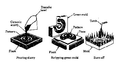
Fig 13 Sequence of operations is making a ceramic mold.
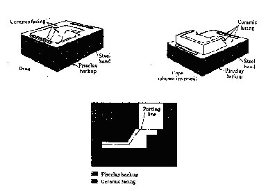
Fig. 14 A typical ceramic mold (Shaw process) for casting steel dies used in hot forging.
Investment Casting
The investment casting process, also called the lost-wax process, was first used during the period 4000-3000 B.C. The pattern is made of wax or a plastic such as polystyrene. The sequence involved in investment casting are shown in Fig 15.
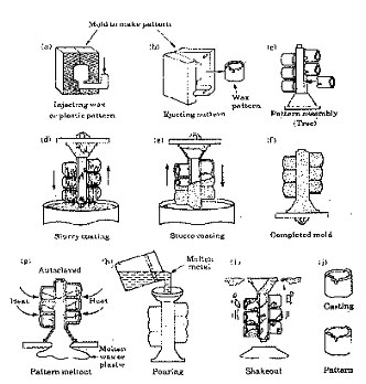
Fig. 15 Schematic illustration of investment castign (lost wax process). Casting by this method can be made with very fine detail and from a variety of metals.
The pattern is made by injecting molten wax or plastic into a metal die in the shape of the pattern. The pattern is then into a slurry of refractory material, such as very fine silica and binders, including water, ethyl silicate, and acids. After this initial coating has dried, the pattern is coated repeatedly to increase its thickness. The term investment comes from the fact that the pattern is invested with the refractory material. Wax patterns require careful handling because they are not strong enough to withstand the forces involved during mold making. However, unlike plastics patterns wax can be resused.
The one piece mold is dried in air and heated to a temperature of 90 - 175°C (200-375°F) in an inverted position to melt out the wax- for about 12 hours. The mold is then fired to 650-1050°C (1200-!900°F) for about 4 hours, depending on the metal to be cast, to drive off the water of crystallization (chemically combined water). After the mold has been poured and the metal has solidified, the mold is broken up and the casting is removed. A number of patterns can be joined to make one mold, called a tree, thus increasing the production rate.
Although the labour and materials involved make the lost wax process, costly, it is suitable for casting high-melting-point alloys with good surface finish and close tolerances. Thus little or no finishing operations are required, which would otherwise add significantly to the total cost of the casting. This process is capable of producing intricate shapes, with parts weighing from 1g to 35 kg (0.035 oz to 75 lb,) from a wide variety of ferrous and nonferrous metals and alloys. Typical parts made are components for office equipment and mechanical components such as gears, cams, valves, and ratchets.
Example : Eliminating porosity in casting
In investment costing of an aluminium-alloy valve body, porosity developed at the core-casting interface. The mold was originally heated to 200°C (400°F), which was too high for the metal around the core to solidify at a sufficiently high rate. Thus the casting began to solidify from the outside wall toward the core, and the gas (hydrogen) expelled during freezing of the metal accumulated at the area near the core-metal interface, thus producing porosity. By lowering the mold temperature to around 90°C (200°F), the metal around the core solidified at a high enough rate to prevent expulsion of gases around the core area, thus eliminating porosity.
Ceramic shell investment casting : A variation of the investment- casting-process is ceramic-shell casting. It uses the same type of wax or plastic pattern, which is dipped first in ethyl silicate gel and then a fluidized bed of fine-grained fused silica or zircon flour. The pattern is then dipped into coarser-grained silica to build up additional coatings and thickness to withstand the thermal shock of pouring. The rest of the procedure is similar to investment casting. This process is economical and is used extensively for precision casting of steel and high-temperature alloys.
If ceramic cores are used in the casting, they are removed by leaching with caustic solution under high pressure and temperature. The molten metal may be poured in a vacuum to extract evolved gases and reduce oxidation, thus improving the quality of the castings. To further reduce microporosity, the casting made by this and other processes are subjected to hot isostatic pressing. Aluminium casting for example, are subjected to a gas pressure up to 100 Mpa (15 ksi) at 500°C (900°F).
Example : Investment-cast superalloy components for gas turbines.
Since the 1960s, investment act superalloys have been replacing wrought counter-parts in high-performance gas turbines. Much development has been taking place in producing cleaner superalloys (nickle-base and cobalt-base). Improvements have been made in melting and casting techniques, such as by vacuum-induction melting, using microprocessor controls. Impurity and inclusion levels have continually been reduced thus improving the strength and ductility of these components. Such control is essential because these parts operate at a temperature only about 50°C (90°F) below the solidus.

Fig. 16 Top rotor was investment cast; lower rotor was cast conventionally.
The microstructure of an integrally investment -cast gas-turbine rotor is shown in the upper portion of Fig 16. Note the fine, uniform, equiaxed grain size throughout the cross section. Recent techniques to obtain this result include the use of a nucleant addition to the molten metal, as well as close control of its superheat, pouring techniques and control of cooling rate of the casting. In contrast, the lower portion of Fig.16, shows the same type of rotor cast conventionally; note the coarse grain structure. This rotor will have inferior properties compared to the fine-grained-rotor. Due to development in these processes, the proportion of cast parts to other parts in aircraft engines has increased from 20 percent to about 45 percent by weight.
Vacuum Casting
A schematic illustration of the vacuum-casting process, or counter gravity low pressure (CL) process is show in Fig 17. A mixture of fine sand and urethane is molded over metal dies and cured with amine vapor. Then the mold is held with a robot arm and partially immersed into the molten metal held in an induction furnace. The metal may be melted in air (CLA process) or in a vacuum (CLV process). The vacuum reduces the air pressure inside the mold to about two-thirds of atmospheric pressure, drawing the molten metal into the mold cavities through a gate in the bottom of the mold. The molten metal in the furnace is at a temperature usually 55°C (100°F) above the liquidus temperature; consequently, it begins to solidify within a fraction of a second. After the mold is filled, it is withdrawn from the molten metal.
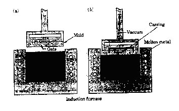
Fig. 17 Schematic illustration of the vacuum casting process. Note that the mold has a bottom gate. (1) Before and (b) after immersion of the mold into the molteon metal.
This process is an alternative to investment, shell-mold and green- sand casting and is particularly suitable for thin-walled (0.75 mm; 0.03 in). complex shapes with uniform properties. Carbon and low-and high- alloy steel and stainless steel parts, weighing as much as 70 kg (155 lb) have been vacuum cast by this method. CLA parts are easily made at high volume and relatively low cost. CLV parts usually contain reactive metals, such as aluminium, titanium, zirconium and hafnium. These parts, which are often in the form of superalloys for gas turbines, may have walls as thin as 0.5 mm (0.02 in). The process can be automated and production costs are similar to those for green-sand casting.
Permanent-Mold Casting
In the permanent mold casting process, also called hard mold casting, two halves of a mold are made from materials such as cast iron, steel, bronze, graphite, or refractory metal alloys. The mold cavity and gating system are machined into the mold and thus become an integral part of it. To produce castings with internal cavities, cores made of metal or sand aggregate are placed in the mold prior to casting. Typical core materials are oil bonded or resin-bonded sand, plaster, graphite, gray iron, low-carbon steel, and hot-work die steel. Gray iron is the most commonly used, particularly for large molds for aluminium and magensium castings. Inserts are also used for various parts of the mold.
In order to increase the life of permanent molds, the surfaces of the mold cavity are usually coated with a refractory slurry, such as sodium silicate and clay, or sprayed with graphite every few castings. These coating also serve as parting agents and as thermal barriers, controlling the rate of cooling of the casting. Mechanical ejectors, such as pins located in various parts of the mold, may be needed for removal of complex castings. Ejectors usually leave small round impression on castings.
The molds are clamped together by mechanical means and heated to about 150- 200°C (300- 400°F) to facilitate metal flow and reduce thermal damage to the dies. The molten metal is then poured through the gating system. After solidification, the molds are opened and the casting is removed. Special means employed to cool the mold include water or the use of fins, similar to those found on motorcycle or lawn mower engines that cool the engine block.
Although the permanent-mold casting operation can be performed manually, the process can be automated for large production runs. This process is used mostly for aluminium, magnesium, and copper alloys and gray iron because of their generally lower melting points. Steels can also be cast using graphite or heat resistant metal molds.
This process produce castings with good surface finish, close tolerances uniform and good mechanical properties, and at high production rates. Typical parts made by permanent-mold casting are automobiles pistons, cylinder heads, connecting rods, gear blanks for appliances, and Kitchenware. Parts that can be made economically generally weigh less than 25 kg (55 lb), although special casting weighing a few hundred kilograms have been made by this process.
Although equipment costs can be high because of die costs, the process can be mechanized, thus keeping labour costs low. Permanent mold casting is not economical for small production runs. Furthermore, because of the difficulty in removing the casting from the mold, intricate shapes cannot be cast by this process. However, easily collapsed sand cores can be used and removed from castings to leave intricate internal cavities. The process is then called semipermanent-mold casting.
Slush Casting
A solidified skin first develops in a casting and that this skin becomes thicker with time. Hollows castings with thin walls can be made by permanent mold casting using this principle. This process is called slush casting. The molten metal is poured into the metal mold, and after the desired thickness of solidified skin is obtained, the mold is inverted or slung, and the remaining liquid metal is poured out. The mold halves are then opened and the casting is removed. The process is suitable for small production runs and is generally used for making ornamental and decorative objects (such as lamp bases and stems) and toys from low melting point metals, such as zinc, tin, and lead alloys.
Pressure Casting
In the two permanent mold processes that we have just described, the molten metal flows into the mold cavity by gravity. In the pressure casting process also called pressure pouring or low-pressure casting, the molten metal is forced upward by gas pressure into a graphite or metal mold.The pressure is maintained until the metal has completely solidified in the mold. The molten metal may also be forced upward by a vacuum, which also removes dissolved gases and gives the casting lower porosity.
Pressure casting is generally used for high quality castings. An example of this process is steel railroad car wheels. These wheels may also be cast in sand molds or semipermanent molds made of graphite and sand.
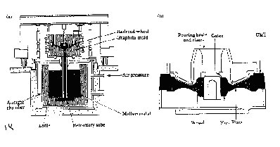
Fig. 18 The bottom pressure casting process utilizes graphite molds for the production of steel railroad wheels.
Die Casting
The die-casting process, developed in the early 1900s, is a further example of permanent-mold casting. The molten metal is forced into the die cavity at pressures ranging from 0.7-700 Mpa (0.1-100 ksi). The European term pressure die casting, or simply die casting. Typical parts made by die casting are carburetors, motors, business machine and appliance components, hand tools, and toys. The weight of most castings ranges from less than 90g (3 oz) to about 25 kg (55 lb). There are two basic types of die-casting machines: hot chamber and cold chamber.
Hot Chamber process
The hot- chamber process involves the use of a piston, which traps a certain volume of molten metal and forces it into the die cavity through gooseneck and nozzle. The pressure ranges up to 35 Mpa (5000 psi), with an average of about 15 Mpa (2000 psi). The metal is held under pressure until it solidifies in the die. To improve die life and to aid in rapid metal cooling-thus reducing cycle time-dies are usually cooled by circulating water or oil through various passageways in the die block. Cycle times usually range up to 900 shots (individual injections) per hour for zinc, although very small component such as zipper teeth can be cast at 18,000 shots per hour. Low-melting point alloys such as zinc, tin and lead are commonly cast by this process.
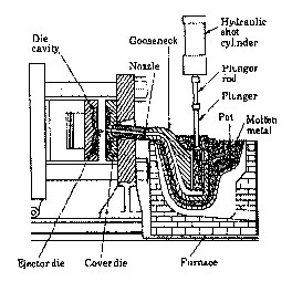
Fig. 19 Sequence of steps in die casting of a part in the hot-chamber process.
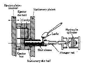
Fig. 20 Sequence of operations in die casting of a part of the cold chamber process.
Cold-chamber process
In the cold chamber process molten metal is poured into the injection cylinder (shot chamber) with a ladle. The shot chamber is not heated- hence the term cold chamber. The metal is forced into the die cavity at pressures usually ranging from 20 Mpa to 70 Mpa (3 ksi to 10 ksi), although they may be as high as 150 Mpa (20 ksi). The machines may be horizontal or vertical, in which the shot chamber is vertical and the machine is similar to a vertical process.
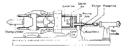
Fig. 21 Schematic illustration of a die-casting machine. These machines are large compared to the size of the casting because large forces are required to keep the two halves of the dies closed. Otherwise, the pressure of the molten metal in the die cavities may force the dies apart.
High-melting-point alloys of aluminium, magnesium, and copper are normally cast by this method, although other metals (including ferrous metals) can also be cast in this manner. Molten-metal temperatures start at about 600° C (1150°F) for aluminium and magnesium alloys and increase considerably for copper base and iron base alloys.
Process capabilities and machine selection
Because of the high pressures involved, the dies have a tendency to part unless clamped together tightly. Die-casting machine are rated according to the clamping force that can be exerted to keep the dies closed. The capacities of commercially available machines range from about 25 tons to 3000 tons. Other factor involved in the selection of the die-casting machines are die size, piston stroke, shot pressure, and cost.
Die-casting dies may be made single-cavity dies, multiple-cavity dies (with several identical cavities), combination- cavity dies (with several different cavities), or unit dies (simple small dies that can be combined two or more units in a master holding die). Typically, the ratio of die weight to part weight is 1000 to 1. Thus the die for a casting weighing 2kg will weigh about 2000 kg. Dies are usually made of hot-work die steels or mold steels. Die wear increases with the temperature of the molten metal. Heat checking of dies (surface cracking from repeated heating and cooling of the die) can be a problem. When die material are selected and maintained properly, dies may last more than half a million shots before any significant die wear takes place.
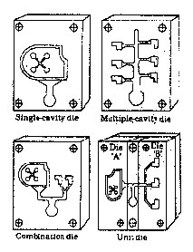
Fig. 22 Various types of cavities in Die-casting dies.
Die design includes taper (draft) to allow the removal of the casting. The sprues and runners may be removed either manually or by using trim dies in a press. The entire die casting and finishing process can be highly automated. Lubricants (parting agents) are usually applied as thin coatings on the die surfaces. Alloys, except magnesium alloys, generally require lubricants. These are usually water-base lubricants with graphite or other compounds in suspension. Because of the high cooling capacity of water, these fluids are also effective in keeping die temperatures low.
Die casting has the capability for high production rates with good strength, high quality parts with complex shapes. It also produces good dimensional accuracy and surface details, thus requiring little or no subsequent machining or finishing operations (net- shape forming). Because of the high pressures involved, wall thicknesses as small as 0.5 mm (0.02 in) are produced and are smaller than those obtained by other casting methods. Ejector marks remain, as do small amounts of flash (thin material squeezed out between the dies) at the die parting line.
Typical small and large parts made by die casting respectively. Note the intricate shape and fine surface detail. In the fabrication of certain parts, die casting can complete favourably with other manufacturing methods, such as sheet metal stamping and forging, or other casting processes. In addition, because the molten metal chills rapidly at then die walls, the casting has a fine grained, hard skin with higher strength. Consequently, the strength-to-weight ratio of die-cast parts increases with decreasing wall thickness. With good surface finish and dimensional accuracy, die casting can produce bearing surface that are normally machined.
Comonents such as pins, shafts and threaded fasteners can be die cast integrally. Called insert molding, this process is similar to placing wooden sticks in popsicles prior to freezing. For good interfacial strength, inserts may be knurled, grooved, or splined. In selecting insert materials, the possibility of galvanic corrosion should be taken into account . Steel, brass, and bronze inserts, for examples, are commonly used in all die casting alloys. If galvanic corrosion is a potential problem, the insert can be insulated, plated, or surface treated.

Fig. 23 Examples of cast-in-place inserts in die casting
- Knurled bushing
- Grooved threaded rod
Table 3 PROPERTIES AND TYPICAL APPLICATIONS OF COMMON DIE-CASTING ALLOYS
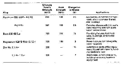
Equipment costs, particularly the cost of dies, are somewhat high, but labour costs are generally low because the process is semi- or fully automated. Die casting is economical for large production runs. The properties and typical applications of common die-casting are given in Table 3
Example: A magnesium-steel assembly replaced with zinc die casting
The transmission selector tube for a Ford automobile, which transfers rotary motion from the column-mounted gear shift to the automatic transmission, was originally made by taking a piece of steel tube, knurling it, placing it in a die, and casting two magnesium heads around it. After a review of this part, It was decided that making it in one piece by ZA-8 zinc alloy die casting would provide sufficient strength to the part, eliminate several operations, and at a manufacturing cost at least $1.50 less than the original part.
Centrifugal Casting
As its name implies, the centrifugal casting process utilizes the inertial forces caused by rotation to distribute the molten metal into the mold cavities. This method was first suggested in the early 1800s. There are three types of centrifugal casting : true centrifugal casting, semicentrifugal casting and centrifuging.
True centrifugal casting. In true centrifugal casting hollow cylindrical parts, such as pipes, gun barrels, and streetlamp posts, are produced by the technique shown in Fig.24, in which molten metal is poured into a rotating mold. The axis of rotation is usually horizontal but can be vertical for short workpieces. Molds are made of steel, iron, or graphite and may be coated with a refractory lining to increase mold life. The mold surfaces can be shaped so that pipes with various outer shapes, including square or polygonal, can be cast. The inner surface of the casting remains cylindrical because the molten metal is uniformly distributed by centrifugal forces. However, because of density differences, lighter elements such as dross, impurities, and pieces of the refractory lining tend to collect on the inner surface of the casting.
Cylindrical parts ranging from 13mm (0.5 in.) to 3 m (10 ft) in diameter and 16 m (50 ft) long can be cast centrifugally, with wall thicknesses ranging from 6 mm to 125 m (0.25 in to 5 in.). The pressure generated by the centrifugal force is high, as much as 150 g's, and that pressure is necessary for casting thick walled parts. Castings of good quality, dimensional accuracy, and external surface detail are obtained by this process. In addition to pipes, typical parts made are bushing, engine- cylinder liners and bearing rings with or without flanges.
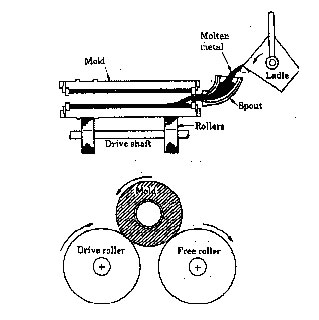
Fig. 24 Schematic illustration of the centrifugal casting process. Pipes, cylinder liners, and similarly shaped parts can be cast by this process.
Semicentrifugal casting. An example of semicentrigal casting is shown in Fig 25. This method is used to cast parts with rotational symmetry, such as a wheel with spokes.
Centrifuging. In centrifuging, also called centrifuging casting, mold cavities of any shape are placed at a certain distance from the axis of rotation. The molten metal is poured from the center and is forced into the mold by centrifugal forces. The properties of castings vary by distance from the axis of rotation.
SQUEEZE CASTING AND SEMISOLID METAL FORMING
There are two relatively new casting processes which are basically combinations of casting and forging (see Chapter 14) namely squeeze casting and semisolid metal forming which we described below.
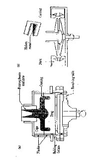
Fig. 25 (a) Schematic illustration of the semicentrifugal casting process. Wheels with spokes can be cast by this process. (b) Schematic illustration of casting by centrifuging. The molds are placed at the periphery of the machine, and the molten metal is forced into the molds by centrifugal forces.
1 Squeeze casting
The squeeze casting, or liquid-metal forging, process was developed in the 1960s and involves solidification of the molten metal under high pressure. The machinery includes a die, punch, and ejector pin. The pressure applied by the punch keeps the entrapped gases in solution, and the contact under high pressure at the die-metal interface promotes rapid heat transfer, resulting in a fine microstructure with good mechanical properties. The application of pressure also overcomes feeding problems that can arise when casting metals with a long freezing range.
Parts can be made to near net shape, with complex shapes and fine surface detail, from both nonferrous and ferrous alloys. Typical products made are automotive wheels and mortar bodies (a short barreled cannon). The pressure required in squeeze casting are lower than those for hot or cold forging.
2 Semisolid metal forming
Also called semisolid, metalworking, semisolid metal forming was developed in the 1970s. The metal or alloy has a nondendritic, roughly spherical, and fine-grained structure when it enters the die or mold. The alloy exhibits thixotropic behaviour, that is, its viscosity decrease when agitated. For example, at rest and above its solidus temperature, the alloy has the consistency of table butter, but when agitated vigorously its consistency is more like machine oils. This behaviour has been utilized in developing technologies combining casting and forging of parts, with cast billets that are forged when 30 to 40 percent liquid. Semisolid metal forming technology was in commercial production by 1981 and is also used in making cast metal-matrix composites.
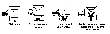
Fig. 26 Sequence of operation in the squeeze casting process. This process combines the advantages of casting and forging.
Another technique for forming in a semisolid state is rheocasting, in which a slurry is produced in a mixer and delivered to the mold or die. However, this process has not yet been commercially successful.
Example : Cast automotive engine component replaced with semisolid forgings.
The aluminium rocker-shaft pedestal for a Chrysler 3.5 L 24-valve V-6 engine was originally designed to be produced by permanent -mold casting; however, the resulting part did not have sufficient strength. The function of this part is to attach the valve-actuation mechanism to the cylinder head. Ductile (nodular) iron was considered for this part, but it weighed three times as much. The process was replaced with semisolid forging in which specially cast aluminium slugs were forged when semisolid, about 50 percent solid and 50 percent liquid. It was found that the forged parts had higher strength, better dimensional accuracy and surface finish, less porosity with better controlled microstructure, and the cost was lower than that for cast parts. The semisolid forging process was also used to make an aluminium timing- belt tensioner-puller pivot bracket for this engine, redesigned from a ductile iron design. The new bracket had good tolerances, did not require any significant additional machining processes, and cost $2.15 less per piece than the ductile iron bracket.
CASTING TECHNIQUES FOR SINGLE-CRYSTAL COMPONENTS
The advantages and limitation of single-crystal and polycrystal line structure-in metals. Let's now consider techniques for producing single crystal (monocrystal) Components . This section will illustrate these techniques by describing the casting of gas turbine blades, which are generally made nickle-base super alloys. The procedures involved can also be used for other alloys and components.
Convertional casting of turbine blades. The conventional casting process uses a ceramic mold. The molten metal is poured into the mold and begins to solidify at the ceramic walls. The grain structuer developed is polycrystalline . The presence of grain boundaries makes this structure susceptible to creep and crackings those boundaries under the centrifugal forces and elevated temperatures common is an operating gas turbine.
Directional Solidified blades. In the directional solidification process, first developed in 1960, the ceramic mold is preheated by radiant heating. The mold is supported by a water-cooled chill plate. After the metal is poured into the mold, the assembly is lowered slowly. Crystals begin to grow at the chill-plate surface and upward. The blade is thus directionally solidified, with longitudinal but no transverse grain boundaries. Consequently,the blade is stronger in the direction of centrifugal forces developed in the gas turbine.
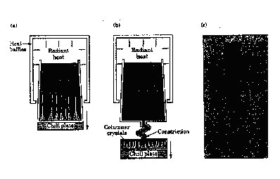
Fig. 27 Methods of casting turbine blades: (a) Directional solidification (b) Method to produce a single construction crystal blade (c) A single crystal blade with the portion still attached.
Single-crystal blades. In crystal growing developed in 1967, the mold has a constriction in the shape of a corkscrew or helix, the cross- section of which allows only one crystal to fit through. The mechanism of crystal growth is such that the most favourably oriented crystals are able to grow through the helix because all others intercepted by the walls of the helical passage. As the assembly is lowered slowly a single crystal grows upward through the constriction and begins to grow in the mold . Strict control of the rate of the movement is necessary. The solidified mass in the mold is a single-crystal blade. Although more expensive than other blades, the lack of grain boundaries makes these blades resistant to creep and thermal shock. Thus they have a longer an more reliable service life.
Single-crystal growing : With the advent of the semiconductor industry single-crystal growing has become a major activity in the manufacture of microelectronic devices. There are basically two methods of crystal growing.
In the crystal pulling method, known as the Czochralski process, a seed crystal is dipped into the molten metal and then pulled out slowly, at a rate of about 10while being rotated. The liquid metal begins to solidify on the seed, and the crystal structure of the seed is continued throughout. Dopants (alloying elements) may be added to the liquid metal to impart special electrical properties. Single crystals of silicon, germanium, and various other elements are grown by this process. Single-crystal ingots typically 50-150 mm (2-6 in.) in diameter and over 1 m (40.in) in length have been produced by this technique.
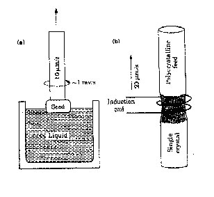
Fig. 28 Two methods of crystal growing (a) crystal pulling (Czochralski process) and (b) floating zone method crystal growing is especially important in the semi conducter industry.
The second technique for crystal growing is the floating-zone method. Starting with a rod of polycrystalline silicon resting on a single crystal, an induction coil heats these two pieces while moving slowly upward. The single crystal grows upward while maintaining its orientation. Thin wafers are then cut from the rod, cleaned, and polished for use in microelectronic device fabrication.
RAPID SOLIDIFICATION ( AMORPHOUS ALLOYS)
Metallic glasses technique involved is called rapid solidification in which the molten metal is cooled at rates as highas, whereby the metal does not have sufficient time to crystallize. Among other effects, rapid solidification results in a significant extension of solid solubility, grain refinement, and reduced microsegsegation. In one method, called melt spinning, the alloy is melted by induction in a ceramic crucible. It is than propelled under high gas pressure at very high speed against a rotating copper disk( chill block) and chills rapidly (splat cooling).
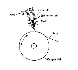
Fig. Schematic illustration of the melt-spinning process to produce thin strips of amorphous metal.
Inspection of castings
Several methods are available for inspection of castings to determine quality and the presence of any defects. Castings can be inspected visually or optically for surface defects. Subsurface and internal defects are investigated using various nondestructive techniques. In destructive testing, test specimens are removed from various sections of a casting to test for strength, ductility, and other mechanical properties, and to determine the presence and location of any defects. Pressure tightness of cast components( valves, pumps, pipes) is usually determined by sealing the openings in the casting and pressurizing it with water, or air. For extreme requirements for leak tightness, pressurized helium or specially scented gases with detectors (sniffers) are used.
The casting is than inpected for leaks while the pressure is maintained. Because air is compressible, its use is dangerous in such tests because of the possibility of a sudden explosion due to a major flaw in the casting.
Unacceptable or defective castings are remelted for reprocessing. Because of the major economic impact, the types of defects present in castings and their causes must be investigated. Control of all stages during casting, from mold preparation to the removal of castings from molds or dies, is important in maintaining good quality.
Melting practice and furnaces
Melting practice is an important aspect of casting operations, because it has a direct bearing on the quality of castings. Furnaces are charged with melting stock consisting of metal, alloying elements, and various other materials such as flux and slag-forming constituents. Fluxes are inorganic compounds that refine the molten metal by removing dissolved gases and various impurities.Fluxes have serval functions, depending on the metal. For example, for aluminium alloys there are cover fluxes, (to form a barrier to oxidation), cleaning fluxes, drossing fluxes, refining fluxes, and wall-cleaning fluxes. (because of the detrimental effect that some fluxes have on furnace linings, particularly induction furnaces.)Fluxes may be added manually or can be injected automatically into the molten metal.
Fluxes for a aluminium typically consist of chlorides, flourides, and borates of aluminium, calcium, magnesium, potassium, and sodium. A typical flux for magnesium consists of a composition of magnesium chloride, potassium chloride, barium chloride, and calcium fluoride. For copper alloys, there are oxidizing fluxes,( which include cupric oxide or manganese dioxide), neutral cover fluxes refining fluxes, and mold fluxes for semicontinuous casting. For zinc alloys, such as in die casting, typical fluxes contain chlorides of zinc, and potassium, sodium. Fluxes for cast iron typically include sodium carbonate and calcium fluoride.
To protect the surface of the molten metal against atmospheric reaction and contamination-and to refine the melt-the pour must be insulted against heat loss. Insulation is usually provided by covering the surface or mixing the melt with compounds that from a slag. In casting steels, the composition of the slag includes CaO1, SiO2, MnO, and FeO. A small quantity of liquid metal is usually tapped and its composition analyzed. Necessary additions or inoculations are then made prior to pouring the metal into the molds.
The metal charge may be composed of commercially pure primary metals, which are remelted scrap. Clean scrapped castings, gates, and risers may also be included in the charge. If the melting points of the alloying elements are sufficiently low, pure-alloying elements are added to obtain the desired composition in the melt. If the melting points are too high, the alloying elements do not mix readily with the low-melting-point metals. In this case, master alloys, or hardeners, are often used. They usually consist of lower melting-point alloys with higher concentrations of one or two of the needed alloying elements. Differences in specific gravity of master alloys should not be great enough to cause segregation in the melt.
Melting furnaces. The melting furnances commonly used in foundries are : electric-arc, induction, crucible, and cupolas.
These furnances are used extensively in foundries and have advantages such as high rate of melting (thus high production rate), much less pollution than other types of furnaces, and the ability to hold the molten metal for any length of time for alloying purposes.
Induction furnace are especially useful in smaller foundries and produce composition-controlled smaller melts. There are two basic types. The coreless induction furnace consists of a crucible completely surrounded with a water-cooled copper coil through which high frequency current passes. Because there is a strong electromagnetic stirring action during induction heating, this type of furnace has excellent mixing characteristics for alloying and adding new charge of metal. The other type is called a core or channel furnace which uses low frequency (as low as 60 Hz) and has a coil that surrounds only a small portion of the unit. It is commonly used in nonferrous foundries and is particularly suitable for superheating (heating above normal casting temperature to improve fluidity), holding (keeping the molten metal at a constant temperature for a period of time, thus making it suitable for die-casting applications), and duplexing (using two furnances, such as melting the metal in one furnace and transferring it to another).
Crucible furnace which have been used extensively throughout history, are heated with various fuels, such as commercial gases, fuel oil, fossil fuel, as well as electricity. They may be stationary, tilting, or movable. Many ferrous and non-ferrous metals are melted in these furnaces.
Cupolas are basically refractory-lined vertical steel vessels that are charged with alternating layers of metal, coke, and flux. Although they require major investments and are being replaced by induction furnaces, cupolas operate continuously, have high melting rates, and produce large amounts of molten metal.
A recent development is levitation melting, involving magnetic suspension of the molten metal. An induction coil simultaneously heats a solid billet and stirs and confines the melt, thus eliminating the need for a crucible, which could be a source of contamination with oxide inclusions. The molten metal then flows downward into an investment-casting mold placed directly below the coil. Experiments indicate that investment castings made by this method are free of refractory inclusions and gas porosity, and have uniform fine-grained structure.
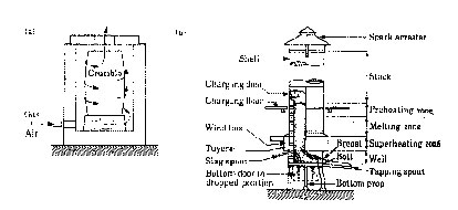
Figure 30. Types of melting furnaces used in foundries : (a) crucible; (b) cupola. The selection of a furnace for a particular application depends on many technical and economic factors.
Furnace selection requires careful consideration of several factors that can significantly influence the quality of castings, as well as the economics of casting operations. A variety of furnaces meet requirements for melting and casting metals and alloys in foundries, so proper selection of a furnace generally depends on :
- Economic considerations, such as initial cost and operating and maintenance costs.
- The composition and melting point of the alloy to be cast and ease of controlling metal chemistry.
- Control of the furnace atmosphere to avoid contamination of the metal.
- Capacity and the rate of melting required.
- Environmental considerations, such as air pollution and noise.
- Power supply and its availability and cost of fuels.
- East of superheating the metal.
- Type of charge material that can be used.
