FIBRE GLASS BLOWN WOOL OR INSULATION PRODUCTS AND THEIR APPLICATIONS
INTRODUCTION-PARAMETERS AND TEST METHODS
Fibre glass behaves as a thermal insulation because of its entrapment of small "cells" of air, and prevention of movement of the air in those cells. In acoustical applications, fibre glass presents to advancing sound waves a myriad of small anechoic chambers which reflect the sound inward from many diverse surfaces until it becomes blotted out. In filtration, fibre glass attracts particles in an air or a liquid stream, preventing their passage and affecting their separation from the stream.
These and many other applications for fibre glass and similar materials are possible because of certain basic technological characteristics briefly described as follows.
Chemical Composition
As discussed, glass melting is possible because of mutual solution at high temperature of a specific, limited group of materials known as glass-forming oxides. Such factors as ease of melting, rapid rate of bubble release from the melt, long working range, and facility of fibreization are important.
In the room-temperature condition for end-use application, the fibre composition should possess good chemical durability and resistance to water attack because of the much larger surface area exposed. It should also accept binder properly, should have a high mechanical strength and lack of friability.
Important test parameters for evaluating and controlling glass compositions are liquidus temperature (point of initial crystal formation out of the melt upon cooling), softening point (temperature at which glass, a thermoplastic, softens and flows under its own weight), density (weight per unit volume determined after controlled thermal history or annealing), rate of flow at the fibre forming temperature (a viscosity test), and seed count (either entrained or dissolved gases being released or incomplete melting). Naturally, chemical analysis by any of several reliable methods is essential for control of both raw glass batch materials and finished melted glass. Periodically it is also advisable to evaluate the finished glass for its chemical durability. This is done by measuring weight loss after exposure of fibres of a known, closely controlled filament diameter to water and to acids and bases of a predetermined normality.
Table 1 : Formulation for Insulation-Type Glasses
| |
Formula for typical mineral or slag wool |
Typical fibre glass insulation compostion |
Typical high-temperature fibre compostion |
| SiO2 |
50 |
63 |
50 |
| Al2O3 |
10 |
] |
] |
| Fe2O3 |
1 |
6 |
40 |
| CaO |
25 |
7 |
6 |
| MgO |
14 |
3 |
4 |
| Na2O |
- |
14 |
- |
| K2O |
- |
1 |
- |
| B2O3 |
- |
6 |
- |
| F2 |
- |
0.7 |
- |
Fibre Diameter
This is the important basic factor as regards specific performance for fibre glass and associated materials, since almost all major end-use behaviour is determined by fibre diameter. Generally product cost increases proportionately with the necessity to create finer filament diameters. The finer-fibreed products will do most of the things that those with coarser fibres will do plus more. Hence end-use requirements should be carefully assessed-if only cold cuts are required, it is not necessary to pay for prime-grade steak.
Table 2 : Filament Diameter Conversion Chart
INCHES
| |
Min. |
Max. |
| AAAAA |
.000002 |
.000008 |
| AAAA |
.000008 |
.00002 |
| AAA |
.00002 |
.00003 |
| AA |
.00003 |
.00006 |
| A |
.00006 |
.00010 |
| B |
.00010[t/d] |
.00015 |
| C |
.00015 |
.00020 |
| D |
.00020 |
.00025 |
| E |
.00025 |
.00030 |
| F |
.00030 |
.00035 |
| G |
.00035 |
.00040 |
| H |
.00040 |
.00045 |
| J |
.00045 |
.00050 |
| K |
.00050 |
.00055 |
| L |
.00055 |
.00060 |
| M |
.00060 |
.00065 |
| N |
.00065 |
.00070 |
| P |
.00070 |
.00075 |
| Q |
.00075 |
.00080 |
| R |
.00080 |
.00085 |
| S |
.00085 |
.00090 |
| T |
.00090 |
.00095 |
| U |
.00095 |
.00100 |
MICRONS
| Min. |
Max. |
| .05 |
.20 |
| .20 |
.50 |
| .51 |
.76 |
| .76 |
1.52 |
| 1.52 |
2.54 |
| 2.54 |
3.81 |
| 3.81 |
5.08 |
| 5.08 |
6.35 |
| 6.35 |
7.62 |
| 7.62 |
8.89 |
| 8.89 |
10.12 |
| 10.12 |
11.43 |
| 11.43 |
12.70 |
| 12.70 |
13.97 |
| 13.97 |
15.24 |
| 15.24 |
16.51 |
| 16.51 |
17.78 |
| 17.78 |
19.05 |
| 19.05 |
20.32 |
| 20.32 |
21.59 |
| 21.59 |
22.86 |
| 22.86 |
24.13 |
| 24.13 |
25.40 |
1 Micron equals .00003937 inches (39.37 millionths of an inch)
Filament diameters and ranges applicable to all fibre glass production are presented in Table 2.
In quality control of fibre sizes for a blown fibre glass production operation, diameters are measured by resistance to air flow using a testing device developed by the Sheffield Micronaire Division of Bendix Corporation. Originally intended for evaluating cotton, this device may be recalibrated for glass fibres. Small standard cyclinders containing a weighed mass of fibres of known diameter and range are used to set or produce one specific air flow rate in the test unit. Following, a weighed portion of an unknown fibre sample is loosely packed into a likesized test cylinder, inserted, and its resistance to air flow measured. The mean fibre diameter of the test sample is smaller or greater than the control standard depending upon whether the sample offers, respectively, more or less resistance to the flow of air.
One difficulty with this measuring system is that the extremes, or degree of fibre diameter distribution under and over the nominal value (3-limits) can not be accurately determined. Nevertheless the method has provided the industry with a good, practical, and duplicatable control of fibre diameter.
Diameters down to 1m may also be measured optically at 1,000 diameters using an accurate projection microscope with calibrated screen. This system is more laborious, required excellent equipment and precise operator technique, but provides extremely accurate results.
Binders
Raw glass fibre in any form, blown bulk or continuous, is brash and easily fragmentized. This is because self-abrasion induced by any kind of motion or rubbing action causes surface defects. These in turn reduce flexural, tensile, and other mechanical strength parameters. The adage is also true with fibres as with other forms of glass that glass is only as strong as its surface.
Consequently, a family of various types of "binders" for mineral and glass wool products has been developed. Applied from 5 to 25 wt% depending upon application, binders are based mostly upon phenol-formaldehyde resins for bonding; they also are formulated to include melamine resins, silicone compounds for water repellency, soluble or emulsified oils for lubrication, wetting agents for control of surface tension, and extenders or stabilizers.
The phenol-formaldehyde resins used are of the strong-base resole (one-step) type, and are water-soluble with a specified dilutability or tolerance of up to 25 volumes of water. Fire-retardant additives are usually reacted in the resin formulation. The resins must be refrigerated prior to use but have fairly long-term (24 hr) stability in the mixed-binder state. The phenolics cure (polymerize) on the glass by chemical action induced by heat (350 to 500øF in the wool; up to 700ø F ambient in the curing ovens). Resin age, pH, percent solids, and degree of cleanliness are important factors in cure.
In the binder formulations used, the end results justify the care and difficulties required in handling. When sprayed on immediately after fibreization or attenuation, the resin accumulates in droplets around the fibres, reaching fibre juctures or simply flattening out along the fibre. Hence both protection against abrasion and resiliency for the final product are provided. The deposition and flattening-out of resin droplets along fibre surfaces, and also accumulations at junctures of two or more fibres are clearly visible in the SEM photomicrograph.
Raw phenolic resins may be tested for cure temperature and time on a standard cure plate. Degree of cure of resin applied to glass wool products may be evaluated by colour (light or pinkish tan-probable undercure, unless artificially coloured; dark tan to brown-good cure), by acetone extration, water absorption, or degree of thickness recovery of the product after prolonged compression. Silicone are evaluated by surface (wetting) angle, and the other ingradients by specific quality and performance tests called out in their manufacturer's specifications.
The amount of binder present is a valuable control parameter and is determined by ignition at 1050ø F of a dry, cured resin-glass sample and then calculating the percent weight loss.
Thickness and Density
These two parameters are so closely interrelated that, in the manufacturing process, a change in one invariably produces a compensating modification in the other. If a machine is producing at 1 in. thickness and 1 lb/cu ft density, and the thickness is doubled to 2 in., the density per inch of thickness would be halved. Hence, the quantity of fibre input to the machine must be doubled to maintain the product at 1 lb density. Since a near-uniform fibre production rate is desirable, the required gain in the fibre input per unit area is accomplished by halving the machine speed, thereby permitting twice as much fibre to accumulate.
In the manufacture of wool fibre, thickness is usually controlled by raising or lowering a set of "flights" or flat semented elements on a chain drive which contact and compress the top surface. These move at the same speed as the bottom or collecting open-mesh converyor. The flights are also constructed of an expanded metal or other openmesh material to permit passage of heated air in the forced-draft curing oven.
Ultimate or specified thickness values of glass fibre and associated wool products are determined by the Gustin-Bacon "measurematic" null-balance device. In this unit the pressure of only a 3g weight ( to depress the few protruding surface fibre) is exerted by a plate which contacts the top of the test sample. Thicknesses vary in fibre glass end products from "in. to as much as 8 in.
The accompanying density in blown fibre glass wool products is determined solely by weight of a sample 1 sq ft in area. Density may be made to vary from 1/2 lb to as much as 7 lb/cu ft in some board products. The upper limit on the flexibile roll goods is approximately 2 1/2 lb/cu ft.
Hence it can be seen that many combinations of wool thickness and density are possible. Most product applications are based upon the best combination of the two to fulfill requirements of thermal, acoustical, or other serice with performance balanced against cost. The close and necessary relationship between thickness and density will become more evident in the ensuing descriptions of individual products and their performance. (Fibre glass product density should not be confused with glass density mentioned earlier. Glass density refers to the fector of increase of the solid glass substance over the weight of an equivalent volume of water taken as unity.)
Percent Shot
As indicated, some of the processes generate a larger percentage of glassy beads or "shot" than others. The shot is often mobile, that is, not attached or adhered to adjoining fibres. Hence it may be removed by mechancial manipulation of a sample and weighed as a quality determination.
Percent Recovery
The degree of recovery in insulation or wool products relates directly to the thickness which the manufacturer guarantees in his finished product specifications. The specifications for the product you want to purchase must be met under any and all conditions.
An austere condition exits in manufacture and packaging of either flat or roll-type insulation products. Unfortunately, they are usually compressed to conserve shipping space.
It would be most disconcerting to allow a 3 in. construction space for insulation, and when the material arrived for installation, find that it filled only a portion of the alloted space. In such an instance, naturally, the thermal efficiency and resistance to heat flow would be different than that originally designed for the building. Therefore, the industry sets and maintains rigid standards for recovery of the products to specified values.
The percent thickness recovery is influenced by the following : the original flight setting (usually original production thicknesses are slightly over specification); thickness itself (greater thicknesses generally have lower percent recovery); density (lower density-lower recovery); tightness of compression, rollup, etc., in packaging for shipment; type, age, formulation, and degree of cure of the bonding resin; and degree of relative humidity in the storage area (packaged insulation should be sealed inside non-moisture-transferring memebranes).
Other Properties
Other functions of fibre glass and related mineral wool products such as resistance to heat transmission (thermal insulation), acoustical or sound absorption, propensity as a filtration medium, and others will be detailed in the ensuing discussions of specific product applications and performances.
BUILDING INSULATION
Thermal Insulation-Homes
Insulation of homes against heat loss (winter) and heat gain (summer) probably represents the largest single usage for fibre glass and mineral wool products. Many different areas of the home may be thermally protected: ceilings, side walls, perimeters of slabs, floors, etc. Not only are many different types of available insulating materials used, but the way various components perform in combination must be taken into consideration in analyzing for the complete insualted structure, either in retrofitting or new construction.
An understanding of the way insulation performs should start with consideration of the basic units of heat and related definitions.
MANUFACTURING PROCESSES
1. GENERAL
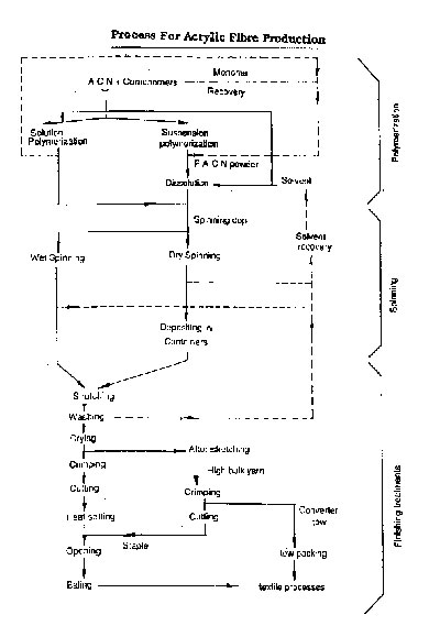
The manufacturing process can be broadly divided into two parts: polymerisation and spinning. Polymerisation process includes copolymer composition, catalyst system, polymerisation reaction and monomer recovery. Spinning includes solution/dope preparation, spring techniques and finishing operations including after treatment, cutting and baling. A general process for acrylic fibre production is given in Figure 1. In the preparation of acrylic and modacrylic fibres, both polymerisation and spinning help to determine the ultimate properties of the fibre. The polymerisation process, determines the composition and molecular weight of the polymer and thus sets the limits on the final properties of the fibre as well as on the spinning process.
2. FACTORS RESPONSIBLE FOR POLYMERISATION
I. Co-polymer Composition: Acrylic fibre manufacture requires acrylonitrile polymer with specific composition. All acrylic fibres contain acrylonitrile (90-94%) and a neutral comonomer. Ionic comonomers are used mainly to improve dyeability of acrylic fibres.
II. Neutral comonomers: Methyl acrylate and vinyl acetate, are used to increase the solubility of the polymer in the spinning solvent and to improve the rate of diffusion of dyes into the fibre.
III. Ionic Componomers: Properties modifying monomers such as ionic monomers sodium styrene sulphonate (SSS), sodium methallyl sulphonate (SMS) to provide supplemental dyesites and to impart differential water sensitivity between elements in bicomponent fibres or halogen containing monomers such as vinyl chloride, vinyl bromide and vinylidene chloride to impart flame resistance.
IV. Molecular Weight: The molecular weight of the polymer is vital since it determines the solution properties of the polymer and rheological properties of the dope, i.e. polymer solution. The molecular weight of the polymer must be low enough so that the polymer is readily soluble in spinning solvents, yet high enough to give dope of moderately high viscosity. Polymers with a very high molecular weight fraction may form insoluble microgels in the spinning solution. Fibre dyeability is dependent on molecular weight distribution of the polymer, since most acrylic fibres derive their dyeability from sulphonate and sulphate initiator fragments, at the polymer chain ends, the dyesite content of the fibre is inversely related to number average molecular weight of the polymer and is sensitive to the fraction of low molecular weight polymer.
V. Catalyst Preparation: The catalysts used are normally solids (ferrous compounds) and are brought in to solution before feeding to the polymerization reactor. The preparation involves weighting of solids, charging of required quantity of de-mineralised water and agitation in a dissolver. After ensuring the correct concentration the various solutions are transferred to storage tanks from where they are metered to a polymerisation reactor at a predetermined rate.
VI. Process Parameters: Properties of the polymer, i.e. molecular weight and dye sites vary, depending on the following parameters:
- Water/monometer ratio
- SO2/persulphate ratio
- Reaction temperature
- Dwell time
- pH of the reactor slurry
- Amount of fe2+ with respect to monomer weight
- Addition of chain-stopper agent
- Agitator's rpm
These parameters are closely monitored and controlled to obtain the desired degree of polymerisation.
3. POLYMERISATION PROCESS
General: In early years of acrylic fibre production, during 1950s and early 1960s, the semibatch polymerisation process was used. In this type process, the reaction vessel was charged with a portion of the reactant and was allowed to proceed by application of heat. Fibre applications required rigorous control of polymer composition and molecular weight. Hence, monomer and initiator components were added during the course for the reaction to maintain as constant a conditions as possible within the reaction vessel.
Processes using continuous stirred tank reactor have replaced the semibatch process except when low volume speciality products are made. Initially, the reactor is charged with a certain amount of reaction medium. The reaction feeds are then metered in at a constant rate for the entire course of production run, which normally continues until equipment maintenance is required. A steady stage is established by taking the overflow stream at the same mass rate of flow as the combined feed streams. An important advantage of this process over the semibatch process is greatly improved control of molecular weight, dry site level, and polymer composition.
Bulk Polymerisation: Pure Polyacrylonitrile has a highly polar and pseudocrystalline structure that makes polymer insoluble in its own monomer. Consequently, when polymerised in bulk, the polymer precipitates from the reaction medium as soon as it is formed. The polymer particles are barely swollen. Therefore, as the reaction proceeds, the precipitated polymer remains dispersed, giving the reaction medium a white, milky appearance. The polymerisation reaction is autocatalytic even under isothermal conditions. Although bulk polymerisation of acrylonitrile seems adaptable, it is rarely used commercially in the fibre industry because the autocatalytic nature of the reaction makes it difficult to control. This feature, combined with the fact that the rate of heat generation per unit volume is very high, make large scale commercial bulk operations difficult to implement. A commercial process of bulk polymerisation has been developed by Montedision.
Aqueous Dispersion/Suspension
I. This is by far the most widely used method of polymerisation in the acrylic fibre industry. In this process, polymerisation is carried out by suspension route using "Redox Couple" (Reduction and oxidation process coupled together) in a medium of demineralised water. When inorganic compounds, such as persulphates, perchlorates or hydrogen peroxide, are used as radical generators, the initiation and primary radical-growth steps occur mostly in the aqueous phase. Chain growth in the aqueous phase is minimal, as polymer is insoluble in water.
II. Redox initiation is normally used in the commercial production of polymers for acrylic fibres. This type of initiator can generate free radicals in an aqueous medium at relatively low temperataures. The most common redox system consists of ammonium or potassium persulphate (oxidizer), sodium sulphite (reducing agent), and ferric or ferrous ion (catalyst). The redox system works at a pH of 2 to 4 at temperature range of 30-60øC. Two main reactions account for radical production.
The sulphate and sulphonate radicals, thus produced,react with monomer to initiate rapid chain growth. Since initiating radicals are incorporated into the polymer chain; they serve as dye-sites for the final fibre product. The dye sites incorporated in this manner are always at chain ends. The dyeability of the fibre is, therefore, strongly dependent on the molecular weight of the polymer, which must be controlled to the desired level. This is commonly done by taking advantage of the chain transfer activity of In commercial practice, an excess of sodium bisulphite or a similar compound is added to the polymerisation mass to yield the desired dye-site incorporation and molecular weight.
A commercial aqueous dispersion polymerisation process employing a continuous stirred tank reactor is illustrated in Figure 2. A monomer mixture composed of acrylonitrile and upto 10 per cent comonomer is continuously fed to the reacter. In addition, aqueous solution of potassium persulphate oxidiser, sulpher dioxide reducing agent and sodium bicarbon ate buffer are also continously fed to the reactor. The aqueous and monomer feed streams may be fed at rates that produce a reactor dwell time of 40-120 minutes and ratio of water to mon omer in the range from 3 to 5. The product, an aqueous slurry of polymer particles is mixed with oxalic acid or ethylene-diamine-tetra-acetic acid (ETDA) to short stop the polymerisation. Monomer is normally recovered by distillation.
FLOW SHEET FOR AQUEOUS SUSPENSION POLYMERIZATION OF ACRYLONITRILE:
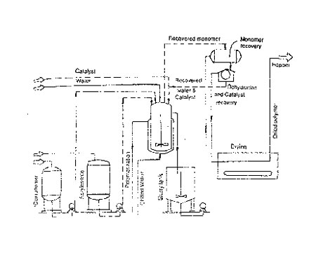
This process gives fairly narrow molecular weight distribuiton because of control of kinetic chain length. This distribution is extremely important for good rheological property and dyeability.
III. The polymerization in water offers the advantage of a high reaction rate, thereby usage of smaller reactors at high productivity levels. Further it possible to prepare polymer dopes of high concentration which are required in dry spinning. On the other hand, there is a disadvantage of having to set up a fairly complex and costly plant for washing, drying, milling and dissolving the polymer in a solvent. This last operation further calls for a careful attention, since polyacrylonitrile powers tend to form swollen lumps which are difficult to dissolve. Sometimes, drying of polymer could also result in dust explosions, and therefore, adequate precautions have to be taken. But, this process gives high degree of conversion better product whiteness, easier control of polymerization and higher dope concentration.
Emulsion Polymerisation
I. Emulsion polymerisation is carried out by stirring monomer in water along with suitable emulsifier and a radical imitiator. It has been shown that emulifier disperses a small portion of the monomer in aggregates of 50-100 molecules, approximately 5 NM in diameter, called micelles. The majority of the monomer stays suspended in droplet form. These droplets are 1000 NM in diameter, much larger than micelles. Since a water soluble radical initiator is used, polymerisation begins in the aqueous phase, followed by rapid absorption of aqueous radicals into nearby micelles. The micelle is essentially a tiny reservoir of monomer. Therefore, polymerisation proceeds rapidly, converting the micelle to a polymer particle nucleus. This particle nucleus continues to grow in size, being supplied with the monomer by diffusion from the monomer droplets.
II. Particles in the typical emulsion polymerisation are less than 1 NM in diameter, much smaller than the 20-50 NM particles normally seen in bulk and dispersion/suspension polymerisation. When two radicals are present in a particle this small radical/ recombination is highly likely. As a result, chain growth begins when the first radical enters the particle by absorption, and ends when a second radical enters. Thus, on an average, only half the particles contain a growing radical at any given time. This unique property is of great commercial importance, because it allows high rates of polymerisation and very high molecular weight. In practice, many commercial processes require a chain transfer agent to control molecular weight. The emulsion polymerisation of acrylonitrile is unique because of acrylonitrile is moderately water soluble and polymer particles are barely swollen by monomer.
III. Although Emulsion polymerisation is not widely used in the textile industry, there are many references to its use in the patent literature. Notable examples are the Union Carbide process for Dynel and a Bayer process, also designed to make modacrylic-vinyl chloride copolymers. In both cases, the emulsion method is used because this monomer pair polymerises slowly and gives low molecular weight products by conventional techniques. Emulsion processes have also be claimed by Mitsubishi, Japan Exlan and Toray Industries.
IV. A potential advantrage of emulsion polymerisation is that the emulsion can be heated to the wet melting temperature of the polymer and melt spun. Modacrylics are more suitable than acrylics because they have lower melting points. Commerical processes have been developed by Du Pont and Asahi. Emulsion polymerisation may also be coupled with emulsion spinning. In this case, the polymerisation is carried out in a emulsion containing both monomer and a solvent such as dimethyl sulfoxide.
Solution Polymerisation
I. Solution polymerisation is widely used in the textile indusry. The reactionis carried out in a homogeneous medium by using a solvent for the polymer. Suitable solvents can be highly polar organic compounds or inorganic aqueous salt solutions. Commonly organic solvent used are : Dimethylformamide (DMF). Butyrolactone, Dimethyl Sulfoxide (DMSO), Ethylene Carbonate, etc. In organic salt solutions are : Zinc chloride solution (60% aqueous), Sodium thiocyanate solution (44-50% aqueous), Calcium thiocyanate solution (aqueous), Perchlorate solution (aqueous), water at high temperature, etc.
II. The advantage of this polymerisation method is that the polymer solution can be converted directly to a spinnable dope by removing the unreactand monomer. However, there are a number of disadvantages.
- It is more difficult to achieve high molecular weight polymer.
- The solvents required are generally chain transfer agents.
- Because of high chain mobility in solution polymeriation, chain termination is quite rapid.
- Incorporation of nonvolatile monomers, such as sulphonated monomers can also be a problem because of their solubility in organic solvents, and must be solubilised by converting them to a soluble form, such as the amine salt form.
- Nonvolatile monomers are also difficult to recover from the reaction medium since the usual distillation techniques are unsuitable. However, the usual practice is to maximize the single pass utilization of these monomers.
III. Thermally activated initiators, such as azobisisobutylonitrile (AIBN), ammonium persulfate, or benzyl peroxide, can be used for solution polymerisation, but these initiators are slow acting at temperatures desirable for textile grade polymer processes. Half lives of this type of initiators are 10-20 hours at 50-60øC. These initiators are, therefore, used mainly in batch or semi-batch processes, where reaction can be carried out over an extended period of time. More active initiator, which also adds sulphonic end groups, is the combination of cumyl, hydroperoxide and sodium ethylsulphide.
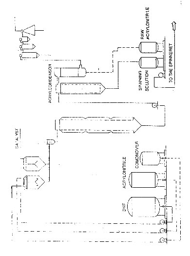
IV. The obvious advantage of the solution process is the considerable savings realised by eliminating the filteration, drying and dope mixing steps required in the aqueous dispersion. Most modern large scale polymerisations are carried out by continuous processes and rapid acting redox initiators are preferred. The process flow diagram is given in Figure 3.
4. COMMERCIAL POLYMERISATION PROCESSES
A summary of the commercial process reported by major acrylic fibre manufactures is given in Table 4.
Table : 1 Commercial Processes Reported by the Major Acrylic Fibre Manufacturers
| Fibre Producers |
Trade name |
Major Comonomer |
Dye sites |
Solvent |
| 1. Fibre Producers Using Aqueous Dispersion Polymerization |
|
|
|
|
| Monsanto |
Acrilan |
VA |
Ionic end groups |
DMF |
| Du Pont |
Orlon |
MA |
Sodium styrene Sulfonate |
|
| Fable |
Acribel |
MA |
Aliphatic sulfonate |
|
| Hoechst |
Dolan |
MA |
Ionic end groups |
|
| Mitsubishi Rayon |
Vonnel |
VA |
Sulfoethyl acrylate |
|
| |
Finel |
MA |
Ionic end groups |
|
| Rhone-Poulene |
Crylor |
MA |
Ionic end groups |
|
| Bayer |
Dralon |
MA |
Ionic end groups |
|
| Asahi |
Cashmilon |
MA |
Ionic end groups |
HNO3 |
| Montefibre |
Leacril |
VA |
Ionic end groups |
DMAC |
| 2. Fibre producers Using Solution Polymerization |
|
|
|
|
| Snia-Viscose |
Velicrene |
MA |
Ionic end groups |
DMF |
| Somex |
Finacryl |
MA |
Ionic end groups |
DMF |
| Toray |
Toraylon |
MA |
Aliphatic Sulfonate |
DMSD |
| Courtaulds |
Courtelle |
MA |
Acrylic acid |
Thiocyanate |
| American Cyanamid |
Creslan |
MA, MMA |
Ionic end groups |
Thiocyanate |
| Nippon Exlan |
Exlan |
MA, MMA |
Ionic end groups |
Thiocyanate |
| Badische |
Zefron |
MA |
Sulfonethyl-Methacroylate |
ZnCl2 |
| Toho-Belson Chloride |
Belson |
MA |
Ionic end groups |
ZnCl2 |
| 3. Indian Companies |
|
|
|
|
| IPCL |
Indacryl |
MA |
Sodium allyl Sulphonate Asahi Plant |
HNO3 |
| |
|
|
Sodium styrene Solphonate Du-pont Plant |
DMF |
| J.K. Synthetic |
Jaykrylic |
VA |
Sod. Methallyl sulphonate |
DMAC |
5. PROCESSING AND SPINNING
General
I. From a processing stand point, acrylic and modacrylic polymers, as a class have the disadvantage of melting at higher temperatures than their decomposition points. Consequently, these polymers have to be spun to fibre from a solution, or, in specialised cases, from a plasticised melt. Commerially, acrylic and modacrylic polymers are spun to fibre exclusively from solutions in very powerful solvents which are:
| SOLVENTS |
% POLYMER |
| Dimethy iformamide (DMF) |
20-32 |
| Dimethylacetamide (DMAC) |
20-27 |
| Dimethylsulfoxide (DMSO) |
20-30 |
| Ethylene Carbonate |
15-18 |
| Sodium Thiocyanate (NaSCN) 45%-55% in water |
10-15 |
| Zinc Chloride 55-65% in water |
8-12 |
| Nitric Acid 65-75% in water |
8-12 |
For inorganic solvents, the proper choice of additives, e.g. Urea to nitric acid, or of salt mixtures can improve dope properties such as viscosity.
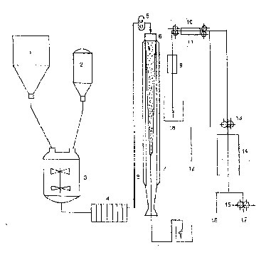
I. Solution/Dope Preparation
- In a typical spinning process, the acrylic polymer is dissolved in a solvent to form a highly viscous solution. i.e. a done. In order to facilitate uniform dissolution of the polymer without formation of gel particles, the polymer is first dispersed in cold solvent to create a fine slurry, which is then dissolved by application of heat and shear in a dope mixer or heat exchanger. Depending on the spinning solvent, spinning dopes have concentrations ranging from 8 to 27 percent.
- From the storage hopper polymer is fed to constant feed weigher by means of rotary values pulverized to fine powder and fed to mixer. Here, the required solvent at desired temperature is added in fixed proportion to the powder quantity fed by a rotary value to give desired polymer concentration and viscosity of spinning solution. This solution is processed through series of grinders, filtration units and de-aerated to remove entrained air bubbles and sent to dope storage tank. From the storage tank dope is pumped to spinning through a set of final filters. A schematic diagram using DMF solvent is given in Figure 4.
- The spinning of acrylic polymers obtained by solution polymerisation, in a suitable spinning solvent, such as dimethyl sulfoxide, or aqueous zinc chlorde, has the obvious advantages of avoiding two process steps, i.e. polymer isolation or drying and subsequent dissolution, and is therefore economically advantageous.
- Another important phenomenon is solution spinning of high molecular weight polymers which is called dope fracture. Analogues to melt fracture, elastic fracture of polymer solutions occurs at a critical extension stress as the polymer solution is accelerated from the wide space behind the spinneret capillary into the capillary itself. Dope fracture leads to severe distortions of the stream exiting from spinneret hole and loss of fibre properties. Special configurations of the entrance to the spinneret capillary can alleviate the severity of solution fracture.
Spinning Processes
The spinning process most commonly used for the production of acrylic fibres is wet and dry spinning. Acrylic and modacrylic fibres cannot be melt spun because they degrade when heated near their melting point. However, some research work has been conducted on the melt spinning of acrylic polymer, by decreasing the melting point with the help of some plasticizers or a solvent. As mentioned above, the melting point of acrylic polymers can also be depressed by the addition of water, through under pressure. Apparently, when polymer water mixture contains enough water to hydrate some of the nitrile groups, the melt can be extruded. However, due to the difficulty in obtaining a stable phase of molten acrylic polymer, melt spinning of acrylic fibres has not been used commercially, only wet and dry spinning is used by the acrylic fibre manufacturers.

1. DMF inlet tank
2. PACN powder container
3. Premixer
4. Dissolving tank
5. Gear pumps
6. Homogenizer
7. After dissolver
8. Elevator
9. Filter
10. Spinning tank
11. Filter
12. Top spinning machine
I. Wet Spinning
- From dope preparation area, the spinning dope obtained is dearated, filtered and extruded through a spinnerette assembly with 10,000 to 60,000 holes with size varying from 0.05 to 0.38 mm. The dope is extruded through the spinnerette into a coagulation bath, normally consisting of solvent and water. Fibre formation occurs rapidly as filaments of the dope coagulates and is drawn out of the bath for subsequent tow processing. Normally several spinnerettes are located in a single coagulation bath and the filaments from these are combined to form a single large tow.
- The coagulated filaments are withdrawn from spin bath by means of a roll. The jet stretch i.e. ratio of roll surface speed to theoretical dope extrusion velocity, creates tension in the emerging filaments leading to a first orientation of the polymer chains. After leaving the first wash roll, the filaments are washed and stretched further by application of an orientation stretch, conventionally called the cascade stretch.
- This washing and stretching procedure is mainly responsible for the implementation of the desired fibre properties- which in turn is a result of careful selection of spin-bath conditions like solvent concentration, temperature and jet stretch.
- After washing and wet stretching, a finish is applied to the filament bundle in order to provide surface lubrication for further fibre processing and to prevent static build up. The fibre bundle is then dried and collected; optionally, the dried and collapsed fibre is subjected to a hot drawing process before collection in order to created a particularly desirable tensile property profile and to reduce diameter-tex or denier -or the fibre or both.
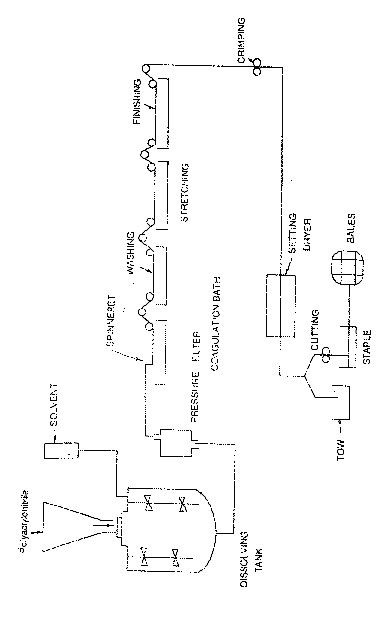
- Because of the inherent brittleness of wet-spun acrylic fibres, the spun filament bundle is normally subjected to an annealing treatment with steam under pressure. Depending on the steam pressure used, a variety of strength and elongation combinations are possible in acrylic fibres for specific uses. Figure 5 shows the schematic diagram of the wet spinning process.
- In wet spinning, the initial gelation and coagulation of the extruding filament are critical for the desired fibre properties. Studies have shown that temperature, composition of the spin bath, jet stretch of the extruding filament during coagulation, concentration of the extruded polymer solution, dope solids and polymer composition influence gelation and coagulation. Studies have further shows that, for the same polymer, gel densities of dry spun filaments were much higher than wet spun filaments and approached that of the collapsed fibre if dry spinning conditions were adjusted to minimum residual solvent at the exit from the spinning tower. It is also observed that higher initial fibre density and more homogeneous internal structure leads to improved fibre strength at lower stretches, higher levels of elongation at a given stretch, high maximum strength and modulus at high stretch ratios, and improved fatigue and abrasion resistance.
- Gelation is a very important step in the spinning of acrylic and modacrylic fibres. According to a study, gelation should precede polymer precipitation for development of a dense homogenous fibre structure that would be desirable for creation of optimum fibre properties. Gelation process is reversible, i.e. gels formed at lower temperatures became fluid again if heated above gel melting point.
- In addition to gelation and coagulation conditions, the rheological properties of the concentrated polymer solution extruded through the spinneret capillary are important for fibre structure, spinning stability, and speed. Because of die swell, a filament extruded from the spinneret will substantially increase in diameter and decrease in line a speed if it is not simultaneously extended by tension imposed by withdrawal of the filament by the first godet. This die-swell caused by the elastic properties of the polymer solution. The extent of the die-swell increases when the apparent shear rate at the capillary wall increases. The freely extruded filament is essentially strain free. Elasticity of the polymer solution has been related to the velocity of a freely extruded filament.
- The maximum speed at which the filaments can be withdrawn by the first godet increases as the linear speed of the freely extruded filament increases. An investigation of the freely extruded velocity is quite useful as the ratio of maximum first godet speed to actual first godet speed at least, partially determines spinning stability. The studies also show that jet hole configuration, dope flow rate, solution viscosity and coagulation conditions are related to spinning stability. Filament breakage in the spin bath occurs because of tension induced throught he die-swell. The Barrus Effect-breaks the load bearing skin of the forming filament, exposing the non load bearing, yet not coagulated liquid core. The apparent draw ratio can be calculated and corresponds to the ratio of actual to maximum first godet speed.
II. Dry Spinning
- In wet spinning, the polymer solvent is removed by diffusion from the extruded filament into the spin bath; simultaneously non solvent enters the filaments, which often leads to formation of undersirable macrovoids in the filaments. In contrast, dry spinning involves removal of the solvent from the extruded polymer-solvent stream primarily by evapouration leading to the formation of highly dense filaments free of macrovoids.
- Dry-spun acrylic fibres normally have a dogbone across section because of initial skin formation on the outside area of initially round filament. Subsequent, further removal of solvent from the interior of the filament by diffusion through this skin causes volume shrinkage of the interior leading to deformation of somewhat rigid skin into a nonround configuration. Round cross sections are obtainable by formation of less rigid skin through use of static zone in the top spinning tower with a high solvent heated gas ratio.
- In dry spinning the dope containing 25-32% polymer in a solvent (commonly dimethyl formamide) is extruded through the spinnerettes down into a tower where uncoagulated filaments are brought into contact with inert gas, heated above the solvent boiling point. The solvent evaporates from the filaments as they pass down the column and solidify. Filament formation occurs through evaporation of solvent which is recovered from the gas stream by cooling and distillation and recycled to dope manufacturing area. The solidified filaments are withdrawn from the dry-spinning chamber by means of a godet at the bottom of the unit. From this godet, the filament bundle is combined to a tow subjected to similar process steps as the wet-spun tow leaving the spin bath. Because of high boiling point of the solvent, (dimethylformamide 153øC), the filaments leaving the dry spinning chamber contain 10-15% of residual solvent, which is removed by washing the tow while stretching it in order to induce polymer orientation in the direction of the fibre axis. Finish is then applied to tow, which is subsequently dried and annealed.
1. PACN
2. Dissolving tank
3. Filter press
4. Pump
5. Spinneret
6. Evaporation chamber
7. Heated wall
8. Washing
9. Stretching
10. Heated chamber
11. Yarn
12. Crimber
13. Setting
14. Cutter
15. Tow
16. Staple
17. Container
- Dry spinning acrylic fibres process uses a limited number of holes, 300-900, per spinneret assembly in order to avoid filament fusion in the dry spinning chamber. The exit speed from the chamber is very much higher 200-400 meters per minute- as compared to 3-10 meters per minute exit speed for wet spinning. However, wet spining bath has large number of holes (upto 60000) per wet spinning spinneret which is an economic advantage of the wet spinning process.
- The parameters favourable for a good dry spun fibre are as below:
(i) Good control of inert gas temperatures
(ii) Good control of take up speed
(iii) Proper control of residual solvent in the fibre
As the take up speeds are quite high (100-500 meter/min) filament bundles are piddled to spun rope cans and creeled later for further processing. A typical dry spun process is shown figure 6.
6. COMMERICAL SPINNING PROCESS
There are eight processes in use for commercial production of acrylic fibres. These are given in Table.
Commercial Process for Production of Acrylic Fibres
| Spinning Process |
Solvent |
Polymer in spinning Solution (%) |
World capacity % |
Major Producers |
| Dry |
DMF |
25-35 |
22 |
United States Europe, Far East Pacific |
| Wet |
DMF |
20-28 |
11 |
Europe |
| Wet |
DMAc |
20-28 |
23 |
United States, Europe, Far East Pacific |
| Wet |
Aq.NaSVN (45-55%) |
10-15 |
23 |
United States, Europe, Russia Far East Pacific |
| Wet |
Aq. HNO (65-75%) |
8-12 |
12 |
Europe, Far East Pacific |
| Wet |
Aq. ZnCl2 (55-65%) |
8-12 |
4 |
United States, Far East Pacific |
| Wet |
DMSO |
20-28 |
3 |
Far East Pacific |
| Wet |
Ethylene Carbonate |
15-18 |
2 |
Far East Pacific |
7. COMPARISON OF DRY/WET SPINNING ROUTES
A comparision between the parameters of wet spinning and dry spinning routes, is given in Table.
Table 3 : Comparison Between Wet and Dry Spinning Processes
| |
Parameter |
Wet Spinning |
Dry Spinning |
| 1. |
Investment Cost |
Low |
High |
| 2. |
Hazard |
Toxic |
Toxic and involve risk of explosion |
| 3. |
Heat input in spinning |
Low |
Very high |
| 4. |
Spinning dope concentration |
20-28% (Polymer) Using DMF, DMAC and DMSO Solvents |
25-35% ( Polymer) |
| 5. |
Range of solvent |
Organic as well as inorganic |
Only organic volatile |
| 6. |
Spinnerette holes |
20,000-75,000 |
300-900 |
| 7. |
Spinning speed (before stretching) |
10-25 mm/min |
200-250 m/min. |
| 8. |
Final speed |
30-90 m/min |
30-90 m/min. |
| 9. |
Stretching |
Integrated |
Separate |
| 10. |
Suitability of the process |
Suitable especially high denier fibre |
Suitable especially fine denier fibre |
| 11. |
Initial stage fibre formation leads |
Low gel-density fibre |
Very high geldensity fibre |
| 12. |
Cross-section |
Round or bean shape |
Dog bone shape |
8. SPECIAL SPINNING PROCESSES
I. Dry-Jet Wet Spinning: In a hybrid method, dry jet-wet spinning, the polymer dope is extruded through a spinneret which is suspended at a short distance, 0.6-5 cm. Above the spin bath liquid. Improved fibre properties and increased spinning speeds are advantages of this process. Although spinning speeds are increased substantially over wet-jet spin ning, in dry jet wet spinning, spinnerets have less than a thousand holes per assembly versus tens of thousands of holes for commercial wet-jet spinning. Dry jet-wet spinning appears to be particularly suited for preparation of continuous filament fibre, which is a fairly small part of the market. In a variant of the dry jet-wet spinning technique, a highly concentrated, hot polymer solution is extruded through a long interval of air, allowing the extruded filaments to cool before entering the spin bath. This treatment permits the extruded stream to gel before coagulation, resulting in fibres that are free from macrovoids.
II. Melt Spinning: From a commercial standpoint, it would be desirable if useful acrylic fibres could be spun from the melt without the use of a solvent which needs to be recovered. Since acrylic degrades when heated above 200øC, plasticizers (10-60% by weight) are used to reduce melting point in order to facilitate melt spinning. The melting point of acrylic can also be depressed by addition of water though this must be done under pressure. With 35% water, the melting point comes down to 185øC instead of 340øC under pressure. All processes involve the spinning of a fusion melt of acrylic polymer with water into a pressurized chamber in a spinning process somewhat similar to dry spinning. Even a process for making hollow filaments by this process has been claimed. Judging from the number of patents issued, the American Cyanamid Co. has extensively investigated this approach.
9. SPECIAL FIBRES
Bicomponent Fibres
(I) In order to obtain wool like aesthetics, elasticity, loft and resistance to permanent heat deformation besides having physical properties of normal acrylic fibres, bicomponent fibres having bilateral or two component structures has been developed. Bicomponent fibres consists of two components divided along the length of the fibre into two distinct regions. The components are selected to shrink or sell differently in response to heat or moisture as a result of which after proper treatement spiral or helical crimp will form. Two different types of bi-component acrylics are:
- Those spun from components containing different amounts of non inonic comonomers (such as vinyl acetate, methylacrylate etc.) giving an irreversible crimp. In this, the crimp is developed irreversibly by relaxing the different shrinkages of the two components by heat treatment during fibre production e.g. during drying or processing (dyeing).
- Those spun from components containing different amounts of ionic comonomers, giving a reverse crimp similar to wool.
According to their structure, acrylic bicomponent fibres can be classified as (I) side by side (S/S) or (ii) Sheath-core types (S/C) with previous being preferred commercially. The two components may differ in chemical composition or in physical properties (molecular wegiht or distribution, viscosity etc.)
(II) In spinning bicomponent fibres, the basic principle is that the two component acrylic polymer are held in separate compartments and brought together just near the spinneret hole. Special type of spinneret for combining these two polymers are required. Both wet and dry spinning techniques are used commercially. However S/S and S/C bicomponent fibre requries different type of spinnerettes.
(III) In producing S/S bicomponent fibre one method employs two polymer solutions supplied in separate channels until at or very close to the spinneret orifices. The relative proportion of the two components are controlled by the rates of feed of the two components to the orifices. Maintenance of pumping pressure, viscosities of two components and precise system of channels leading to orifices is requried. Turbulance must be prevented as the fibres are joined in one stream. Second method of S/S bicomponent fibres combines two components in alternate layers or alternate concentric rings. The non turbulent mixed stream is then reduced in diameter and fed to a orifice aligned to intersect the interfaces of the layer of polymer. The non-turbulence, relative rates of feed, number of rings of orifices equalling the number of interfaces, and the alignment of orifices are critical in this method. Third method employes mixed polymer stream with many interfaces is fed to spinnerette containing many orifices wihch are not aligned with respect to polymer interfaces. Proportion of two components varies between 0 to 100% in the final fibre, though the composition along the length will remain constant due to non turbulance. Higher productions are achieved by using this method.
(IV) Production of S/C type bicomponent fibres is similar to group 1 method discussed above to give concentric (to give non-self crimping fibre) or eccentric ( to give self-crimping potential). Eccentricity may be achieved by off-setting the two extrusion orifices and by controlling the feed rate of two polymers. Further eccentric sheath-core fibres are produced by single component stream which is merged with a concentric sheath-core component. Processing for producing S/C bicomponent fibres has been patented by extruding core as a mono component fibre and then passing it through a solution of second component.Evaporation of solution deposits a sheath on to the core.
(V) These fibres have resiliance and bulk equal to those of wool and hence it has been used in large quantities as a substitute for wool in the world market. These fibres are popularly used in knitting and carpet industry.
Porous fibres
(I) Porous acrylic fibres have been prepared by inclusion of a polymer non-solvent or gases in the spinning dope. The use of multifunctional alcohols such as glycerol or tetraetylene glycol as dope additive is thought to be used in the commercial production of a moisture absorbant fibre like Bayer's Dunova. Tubular fibres for use in reverse osmosis have also been prepared by wet-spinning technique.
(II) Various non aqueous coagulants have been tried in wet-spinning from organic solvents to improve fibre properties. These are glycol, hexanetriol, DMF-cumene mixture etc. Addition of surface active agents to the spin bath liquid has yielded a more uniform and less brittle fibre.
10. DYEING OF ACRYLIC FIBRES
(I) Acrylic fibres are dyed mainly with cationic dyes. Bright, fast colours are achieved that have high esthetic appeal. Disperse dyes can also be used to get a good range of colours, not as bright. A small quantity of acrylic spun from special polymers containing basic groups is dyed with anionic dyes. The mechanism of dyeing with cationic dyes has three steps; surface adsorption, diffusion into the fibre and dye fibre bonding.
(II) The fibre is readily dyed as staple (stock dyed), in yard on cones (package dyes) or as skeins. As previously mentioned, some are dyed during fibre spinning (producer dyed) or as tow; using special tow dyeing equipment. Fabric or garment dyeing (piece dyeing) is used on acrylic knitted goods.
(III) Transfer printing is a recently developed process in which sublimeable dyes are transferred to the fabric by heat from a printed design on paper. Though, acrylics in general are not suitable for this process, current research offers promise for the future. Dyeing in non aqueous liquid (solvent dyeing) is also a useful process for colouring acrylics, fibre or fabric distortion is reduced as is loss of fibre luster. Both processes require less energy than aqueous dyeing and greatly reduces water pollution.
11. POLLUTION CONTROL IN ACRYLIC FIBRE PLANT
(I) Solid effluents generated in an acrylic fibre plants are very less in quantity. These are normally treated by providing an incinarator in the plant.
(II) The process operations are carried out in a closed system and gaseous effluent do not pollute the air. For example, when DMF is used as a solvent, DMF vapour cannot be released in the atmosphere because if DMF content is more than 100 ppm, it will be hazardous to human being. For this purpose, plant is designed to have maximum recovery of DMF by use of a three stage scrubber during operation. A standard of 10 ppm is acceptable in developed countries. IPCL has achieved a standard of 5 ppm.
(III) The effluent water coming out of plant may contain traces of acrylonitrile, co-monomer, solution or catalyst used in the process. The limit value prescribed for acrylonitrile is 0.5mg/m3 The smell of acrylonitrile irritates eyes and nose. Excessive quantity of vapour causes headache, nausea, abdominal pains, vomiting etc. Limit of methyl acrylate concentration is 20 mg/m3. It irritates eye, provoke a lachrymation action and causes dermatitis.
(IV) An effluent treatment plant designed for the depuration of chemical and cloacal effluents coming from the process plants for the production of acrylic fibres and from the connected services is carried out in two phases : Ist phase is of mechanical treatment to triturate suspended solids. 2nd phase is of neutralization and equalization which consists of collecting, accumulating and subsequent removal of chemical and cloacal effluents coming from process plants. This is done by automatic neutralization. The second stage is biological treatment and includes bacterial digestion of dissolved organic substances, effluent clariflocculation, effluent sterilization and sludges elimination.
These treatment eliminate almost totally organic dissolved matters and, therefore, allow the observance of limit requested for COD concentration. Moreover, they eliminate ACN and DMF almost totally.
12. RAW MATERIALS
Acrylonitrile
(I) In India, presently ACN capacity is 24,000 tons/annum produced by IPCL. Baroda. W.B. I.D.C. has acquired LOI for producing 60,000 tons/annum and has gone for collaboration Reliance Industries Ltd. has also acquired another LOI for 60,000 tons/annum. Recently Government of India has increased MES to 70,000 TPA and hence both the companies holding LOI may enhance their capacity to 70,000 TPA. J.K. Synthetics Ltd. Kota is also considering the proposal for putting up an ACN plant. Among these proposed projects none has come to an implementation stage.
(II) ACN transportation and storing needs utmost care. This needs addition of inhibitors in CAN alongwith special storing facility with temperature control and nitrogen blanketing. Transportation is also equally problematic. CAN is basically a toxic chemical and also hazardous to handle. Indian Bureau of Standards has developed a safety code which describes different norms like occupational health norms, storage norms, handling norms, transportation norms, fire prevention and fire fighting norms, slippage and leakage norms, waste disposal norms etc.
Methyl Acrylate and Vinyl Acetate
I. Methyl Acrylate: Most of the acrylic fibre manufacturers use methyl acrylate (MA) as second non ionic co-monomers. So, far, in India, IPCL and Raj Prakash Chemicals are the only manufacturers of methyl acrylate having capacity of 4850 tons/annum. Apart from acrylic fibre industry some other industries like leather, paper adhesive etc. also use acrylates. Taking an average of 8% methly acrylate content in acrylic fibre requirement of MA only for acrylic fibre in 1994-95, 6400 tonnes/annum which is expected to be much higher in 2005-2006 AD. Hence, a short fall of MA supply is expected unless production capacity increase takes place.
II. Vinyl Acetate: Among the present acrylic fibre manufacturers only J.K. Synthetics Limited uses vinyl-acetate as non ionic co-monomers. In India, Vam Organic Chemicals Ltd. And Polychem Ltd. are the only manufacturers of VA having production capacity of 15,000 TPA and 10,000 TPA. Besides, Vinyl Chemical (India) ltd. and Jagatjit Sugar Mills Ltd. are planning to put VAM plants of 10,000 TPA each. Also VAM Organics and Polychem are expanding their capacity form 15,000 TPA to 20,000 TPA. Vinyl acetate is used by several other industries also, like, polyvinyl alcohol, textile, PVA emulsion etc..It is expected that even after expansion of J.K. Synthetics acrylic fibre production capacity, there would not be much shortfall of vinyl acetate availability in India.
Ionic Comonomers
Ionic comonomer differs from process to process. It is believed that sodium allyl sulphonate is used by IPCL for its old plant using Asahi technology.
With Du Pont technology the ionic comonomer is sodium stryrene sulphonate (SSS) which is used by IPCL and will be used by Indian Acrylics Ltd. with Snia-visocsa technology, the ionic third co-polymer is sodium allyl sulphonate; so Pasupati Acrylon ltd. Will be using SAS. J.K. Synthetics Ltd. Collaborated with Monte Fibre in which ionic comonomer is M.A.S.S. Total content of ionic comonomer is acrylic fibre is very less, about 1 to 1.5% only. Most of the ionic comonomers are not produced in India.
Solvents
I. Dimethyl Formamide: In India, IPCL is using DMF as solvent for its new acrylic fibre palnt. Among others, Pasupati Acrylon ltd. and Indian Acrylic ltd. also use DMF as solvent for thier palnts. Presently, in India, acrylic fibre producers are import dependent for this material. Two companies namely M/s. RCF and M/s. Vam Organics are holding LOI for manufacture of DMF. Their details are:
1. M/s Rastriya Chemicals and Fertilizers Limited, Dist. Raigarh, Maharashtra.
Capacity : 2500 TPA
Project Cost : Rs. 60 million
2. M/s. Vam Organic Chemicals Ltd., Dist. Muradabad, U.P.
Capacity : 5000 TPA
Project Cost : Rs. 85 million
LOI issued : in July 1987
II. Dimethyl Acetamide: J.K. Synthetics ltd. Uses DMAc for its production. Total requirement of DMAc for acrylic fibre production at a capacity of 24,000 TPA will be around 1300 TPA. In India, availability of DMAc is almost negligible hence J.K. Synthetics ltd. is totally import dependent for DMAc supply.
III. Nitric Acid (HNO3): IPCL's first plant based on Asahi technology for acrylic fibre production uses nitric acid as solvent. Nitric acid is used by different industries. Nitric acid is indigenously available in India. IPCL procures it from M/s. Rashtriya Chemicals and Fertilisers.
Other Additives and Catalyst
Process to process, the requirement of additives and catalyst varies and the acrylic fibre producers are very secretive about the additives and catalysts. However, total requirement of additives and catalysts is quite insignificant. Normally titanium dioxide is used for delustering agent, halogens are used as fire retarding agents.
13. MAJOR CAPITAL EQUIPMENTS
Suspension Polymerization Parts
1. ACN, Co-monomer Storage Tanks
2. Polymerization Reactor
3. Slurry Hold Tank
4. Monomer Stripping Column, Condensor and Decanter
5. Rotary Vaccum Filters
6. Pelletizor
7. Tunnel Dryer
8. Grinder
9. Polymer Storage Silos
10. Dope Dissolution, Premixer, Homogenizer and Filter.
Solution Polymerisation parts
1. ACN, Co-monomer Storage Tanks
2. Polymerization Reactor
3. Acryl Condensor
4. Thin Layer Evaporator
5. Spinning Solution Tank
Wet Spinning parts
1. Pressure Filter Assembly
2. Spinning Gear Pumps
3. Spinneretts
4. Coagulation Bath
5. Washing, Stretching and Finishing Sections
6. Crimpers
7. Setting Dryer and Thermosetting Autoclaves
8. Cutting Equipment/Stretch Breaking Equipment
9. Baler
Dry Spinning parts
1. PACN/Solvent Dissolving Tank
2. Filter Press
3. Pumps
4. Spinneretts
5. Heated Evaporation (Solvent )Chamber
6. Stretching (heated) section
7. Crimpers
8. Setting Dryer
9. Cutter
10. Baler
CONTINUOUS-FILAMENT FIBRE FORMING METHODS
INTRODUCTION
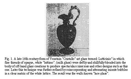
Historically, the continuous-filament type glass antedates the wool variety by quite a few centuries. Syrian and like period glass makers pulled fine threads onto tooled or off-hand glass objects for purposes of decoration. Venetian glass artisans incorporated different coloured glass strands (mostly white) in crossed or web like configurations into the body of their fine, thin-walled objects. Both French and German craftsmen in the mid-18th century learned to produce separate fibers of glass, the German process drawing monofilaments to the side from a hot melt.
Numerous laboratory curiosities simulating fiber-drawing equipment were as common as the earlier Prince Rupert drop or Bologna phial. A resistance-heated platinum strip was arranged with a hole in the center, slightly bent into a boat shape to hold molten glass, and a small hole in the center through which the melted glass would exude. When heated, the glass could be pulled away as a tiny filament by action of a high-speed winding drum.
Just before the turn of the century in 1893, the Columbian Exposition was held in Chicago in which the most effective glass entrepreneurs in U.S. history, Messrs. Edward Drummond Libbey and Michael J. Owens, exhibited many utilitarian glass items including a fiber glass dress.
As stated, commercially important continuous-filament fiber glass products and technology resulted from the joint Owens-Illionis and Corning Glass works research which culminated in formation of a manufacturing facility in 1937. The entire field has expanded at an enviable rate between 15 and 25% per year almost every year since inception.
The development of continuous-filament forming methods is documented in this section. Other related methods of producing fiber glass textiles are included.
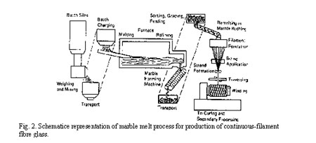
MARBLE MELT PROCESS
The very first fiber glass bushings contained 51 holes or tips (50 for use and 1 spare tip). Marbles from a seperate melting operation were fed to a crucible or fabricated platinum bushing, which was oriented vertically and about 7 in. high. The E-glass borosilicate composition, found necessary to improve over the properties of A-soda-lime glass, dates from the 1930-35 period.
Bushings containing 102 and 204 holes were developed in rapid succession, and standards for weight-length relationship (yards per pound, strand count, or glass "cut") were established.
The base yardage, designated by letter and coordinated with filament diameter range, was originally related to yards per pound for a 200 filament strand. The Tex designation (inverse to yards per pound) is now of international importance.
Fig. 2 presents a schematic diagram of a marble melt process with the glass tank marble production visibly separated from the marble melt bushing. The bushings are aligned in rows and marble distribution stations are located above for gravity feed. Bushing temperatures are nominally 2300øF for remelting E-glass. Following fiberization, the glass filaments are passed over a roller or belt mechanism for organic or other sizing application. These sizing solids are present in amounts less than 2% by weight of the finished product, but dictate end use of the glass fiber product. Sizings require cure by oven drying prior to secondary processing.
The filaments are directed conelike into the vortex of a mechanical gathering device to establish the actual strand. Traversing mechanisms rapidly oscillate the strand as it is drawn into the winding drum, the latter drawing the filaments downward at approximately 2 miles/min surface speed. This high speed is necessary for attenuation to required filament diameters.
As time and technology progressed, the number of bushing holes was increased and portions of the filament bundle were subdivided or "split" to form finer-denier yarns within the same or separate forming packages.
The direct-melt process was a normal consequence to technology gained in marble melt, with 400 and 800 hole bushings employed. However, one parting shot interjected by the marble process was the development of bushings with excessively high tip numbers. These were employed for production of fine-filament B fiber (3.2m nominal filament diameter). The reason was that larger bundles of filaments were required for proper denier of the fine B-yarns which would provide "soft" feel and desirable handling properties required for decorative, bedding, and clothing yarns.
The technology acquired with the B-fiber development in marble bushings was of distinct assistance in development of larger bushings and creation of more versatile fiber glass product types from the direct-melt process.
DIRECT-MELT PROCESS
In Fig.3 is presented a schematic diagram of the direct-melt process. The bushings are aligned on the underside of channels and forehearths directly connected with the glass-melting furnace.
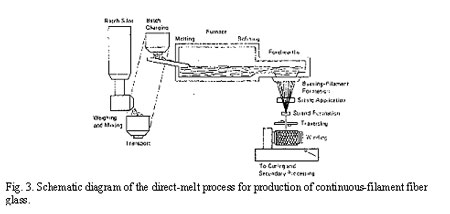
Whereas the glass depth within the furnance is 36 to 48 in., depending upon size, glass level height over the fiberizing units is only approximately 9 in. Hence, lesser dimensional bushing heights in direct melt are required than those for marble melt.
Bushings are arranged so that the fiber-winding mechanisms exist in rows in a "forming room" with vertical fiber-drawing components similar to those for the marble process. Automatic fiber-conveying means out of the forming room are provided. Water, the universal solvent, coolant, and lubricant, is copiously applied at several points in the process to assist the fibers in being drawn over the mechanical components without damage.
Direct-melt type bushings up to 2400 and more tips are now extant, with larger, better performing units on the drawing boards.
Several interesting variations have been spawned as adjuncts to continuous-filament fiber glass production methods. It has always been desirable to produce larger or more usable strands direct from the fiber glass production bushings.
Hence, technology for producing multifilament roving packages and also for direct chopping into short fiber lengths from the bushing has been developed. Previously both were processes requiring interim drying and finishing steps.
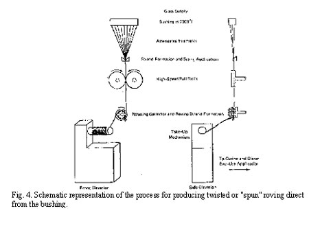
Also, processes were devised for winding a single, 204 or 408 filament strand into a "spun" roving package (see Fig. 4 and for forming a continuous-filament mat using oscillating impact plates).
THE STRICKLAND PROCESSES
Unique attempts to greatly reduce quantities of platimum required for glass fiberization were successfully achieved by one inventor. Originally a pressure system and ultimately a gravity throughput method, the second most important design paramenter was the great increase in tip density,or number of holes per unit of fiber-producing area. The process is highly properietory and probably not yet the source of a major fiber glass production facility.
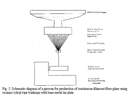
FIBRE PRODUCTION FROM CERAMIC CRUCIBLES
Numerous attempts have been made to produce fiber glass at lower cost from melts made in fired clay or ceramic crucibles. The glass source has been either marbles or cullet remelted by a combination of gas and electric booster melting. An inconel melting plate has been used instead of any platinum. Minimum practical filament diameter is 25.4m (0.001 in.), and the clay pots are fairly short lived. One advantage is that filaments which become broken out and bead down can be refed into the main strand.
The latest attempt is well documented in one of the recent SPI RP/C Technical and Management Conference Proceedings.
METAL COATED GLASS FIBERS
Many combinations of glass or glass fibers and ceramics with metals have been proposed and developed. The main objects have been to render a normally dielectric material partially conductive for certain electrical applications. Other applications of military importance have been developed.
STAPLE FIBRE OR SLIVER
The development of sliver (at least in America) occurred during the period of early experimentation after wool products were known and prior to finalization of continuous filament.
After it had been shown that blown fibers could be produced by attenuation of fine streams of glass using an air or steam blast, and prior to the complete adaptation of platinum as a crucible material, the galss melting for fiberization was carried out in small furnaces made of clay and like refractory materials into which holes had been drilled. Difficulties were experienced with continuing production in the clay refractory crucibles due to enlargement of the holes by action of the hot glass. This naturally changed the blown sliver properties, and in time, even the ability to attenuate the glass.
Also, the sliver product was unacceptably low in strand tensile strength. Continued action by the group looking for higher-strength fibers resulted in the final successful adaptation of platinum and ultimately the continuous-filament fiber glass which provided a more adaptable textile material.
It was discovered that if the random fiber accumulation from a single wool unit was slowly removed in a lineal path, and a slight superficial twist applied, a loosely carded glass sliver strand resulted. This could be compacted, twisted, plied, etc., to form strands for weaving.
While one faction of the groups involved in fiber glass development preferred to utilize this readily available strand woven into cloth and used for electrical laminates, the other group sought to press for development of the continuo8us-filament material.
The platinum technology was, of course, eventually applied to the applicable wool-producing units, and use of sliver continued for electrical and other textile uses in which high strand tensile strength was not the prime requisite. The original production equipment for staple fiber has not changed appreciably since its inception.
Staple fiber development in Europe occurred just before or during World War II in Germany (by Schuller) when asbestos substitutes were drastically needed. A process was developed in which fibers from a 1 m long bushing were attenuated by action of a drum revolving at high speed, with its main shaft located in the same plane as the longitudinal axis of the bushing. The fibers wrapped around the face of the drum and were removed using a doctor blade and passed to the side through cones in which the loose-packed sliver strand was formed.
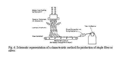
In Fig. 6 is presented a schematic view of one characteristic process for production of staple fiber yarn. Fibers are rapidly attenuated downward from either a marble or batch-reduction melt, and are collected by air suction or other means along a moving belt or drum. They are then immediately formed into a loose, bulky strand.
The fibers are approximately 15 in. long, and roughly or loosely bonded by circumferential twisting, oil application, or other means. There are extremely wide variations possible in denier, as governed by the speed of the take-up. Sliver fiber products enjoy wide usage in many fields.
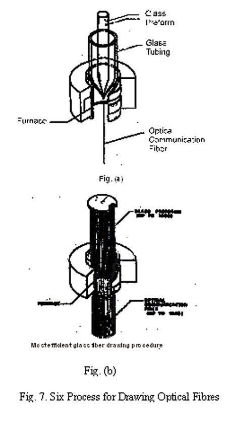
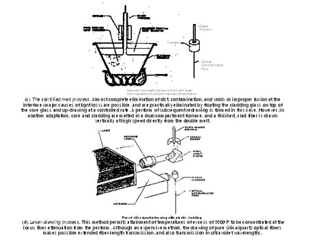
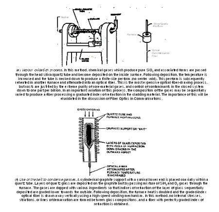
PRODUCTION OF FIBRE OPTIC ELEMENTS
Reverting almost to the original methods for producing glass mono-filaments from heated rods, this process, with substantial improvements, has become important again for producting fibers for visual fiber-optic and fiber electro-optic applications. The main differences are that glass compositions of extremely high purity are necessary for successful use of the ultimately produced filament. The compositions are established, the material is fused into a cylindrical "buhl" or perform and a filament or group of filaments drawn down under very carefully controlled conditions. Sophisticated methods are employed for producing jacketed or clad glass preforms (two or more glass compositions), and higher temperature compositions such as silica-quartz are drawn using a laser process.
EXTRUSION-FUSION METHOD
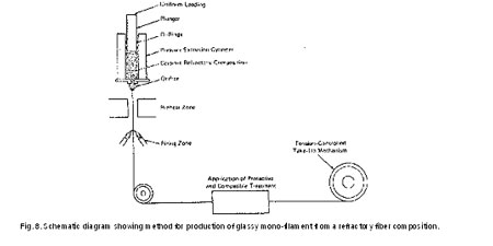
A method for production of a glassy monofilament starting with a refractory ceramic composition was elucidated by IIT researchers. The mechanical components are illustrated schematically in Fig. 8. Obviously, the reduction of a ceramic body and subsequent fusion into the glassy state would necessarily have to proceed at a pace slow enough to preclude this from ever being a viable mass production technique.
Methods of depositing either single-crystal whiskers or vapour-phase material onto a metal fiber substrate to form a continuous filament are also described in the same paper.These fibrous products are usually crystalline and not glassy, however.
PRODUCT APPLICATION
OPTICAL GLASS
Definition
Optical glass is a high glass material that has been specifically formulated to posses certain desirable characteristics that affect the propagation of light. Optical glass differs from ordinary glass with respect to the extreme care and precise control exercised during its manufacture, so as to ensure perfect homogeneity, freedom from colour (except where certain oxides and elements are deliberately introduced for the manufactured of coloured glass) and faithful reproduction of the physical properties from batch to batch. Optical glass must meet a number of important criteria. It must be highly transparent over the visible spectrum. It must also be optically homogeneous, inclusion free, and free of striae and strain. In addition optical glass must have accurately defined optical constants that have only a small temperature dependence. The mechanical strength of optical glass must be sufficiently high so that optical components made from them can be easily handled during manufacture and assembly. Resistance to chemical attack is another important requirement for optical glass.
Types of optical glass
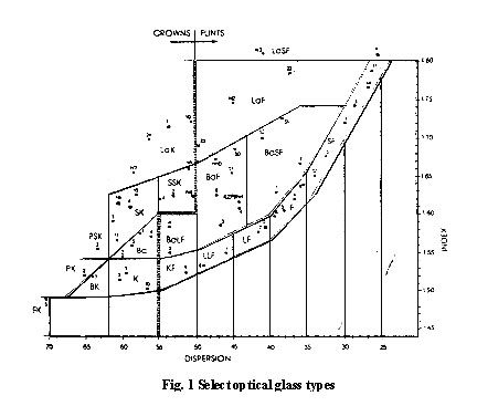
The two primary parameters that define the basic types of optical glass is its refractive index and its dispersion. The Refractive index n is a measure of the refractive powers of the glass relative to air which has an index of 1. The dispersion, expressed by the Abbe number v, is a measure of the dispersive power of the glass. It defines how the glass affects light at different wavelengths.
The optical glasses are broadly classified as crown and flint. There are well recognized further subdivisions under each category, some of which are indicated under showing their abbreviated forms within brackets.
- Crown: Flour Crown(FC), Boro-Silicate(BSC), Light Barium Crown(LBC), Medium Barium Crown(MBC),Dense Barium Crown(DBC) and soft Crown (SC) and others.
- Flint: Telescope Flint (TF), Barium Light Flint (BLF), Barium Flint, (BF), Light Flint (LF), Dense Flint (D), Extra-Dense Flint (EDF), and Double Extra-Dense Flint (DEDF) and others.
Glass types with an nd ] 1.60 and an vd ] 50, as well as those with nd [ 1.60 and vd ] 55, are called crown glass. They have a letter designation K.Glass types with nd ] 1.60 and vd [ 55 are called flint glasses, with the letter designation F. This delineation is shown on the nd|vd figure 1. A uniform method of identifying glass types has been accompolished with the now universally accepted six-digit glass code.
This simple code uniquely the basic optical characteristics of each glass type. The first three digits are derived the refractive index which are the first three significant digits of that product. This sounds a bit complicated, but it is really quite simple. It is best explained by an example.
The refractive index of BK 7 is nd = 1.5168. If 1 is subtracted from this value and the result rounded to three digits, it is 0.517. The first three significant digits are 517. The Abbe number for BK 7 is vd = 64.17 which is first multiplied by 10 and then rounded to the nearest integer. This yields 642. The combination of these two numbers results in the glass code. The convention is not to hyphenate this code, so the code for BK 7 is 517642.
Although the optical parameters must be known to the optician, they are primarily for the purpose for material identification. They do not help in deciding how to best handle and process the glass . It is quite reasonable to assume that different parts made from the same glass, say, BK7, can be treated in similar fashion, but it is not necessarily true that the same assumption holds true for all other glasses of the BK group. More information is needed.
The glass catalogue of the optical glass manufactures provide this added information in the form of data relating to the chemical, thermal, and mechanical behaviour of the glasses. Data on chemical behaviour are very important for polishing, handling, and storage of finished optics. Thermal data can provide clues on how carefully a particular glass be treated during manufacture and data on mechanical characteristics of glass can be helpful during the shaping and grinding stages.
International manufacturers like Schott and Hoya manufacture almost 250 types of glasses( ranging in refractive indexes from 1.43 to 1.96 and abbe numbers ranging from 20 to 90, Ohara in its catalogue mentions around 111 types of glasses( 93 types are free of lead and arsenic) against around 28 types (refractive index ranging from 1.51 to 1.71 and abbe number ranging between 29 to 64) being manufactured by CGCRI. The broad classes of glasses manufactured by some of the manufacturers are given in the enclosed table 1.
Internal Quality Grades
Every glass manufacturer uses a grading scheme that is applicable only to its glasses. The factors on which grading is done include refractive index tolerances, abbe numbers, homogeneity, stress birefringence, striae, bubbles and colouring. In addition thermal, chemical and mechanical properties are also graded. Some efforts in standardising glass grades have been made. One such example into five quality grades and grading is based on the internal quality of the glasses. This standard is used by Schott.
The standard quality N has been tested in one direction for striae and strain. The refractive index ne must not vary by more than = 0.0001 within a melt. This quality grade is useful for photographic lenses, scientific instrumentation, and reproduction optics.
Quality grade NVH is a standard quality glass with improved homogeneity. The refractive index ne varies within the melt by less than = 0.00002, which makes this grade useful for high-quality photographic lenses, scientific instrumentation, and reproduction optics.
Quality grade NSK is a standard quality optical glass with special annealing characteristics. The strain in this type of glass is especially low or it has been brought deliberately to a specific value. This expensive glass is typically used only for astronomical refractive optics.
Grade NVS is a standard grade glass with critical striae selection. This glass is especially low in striae. It is used for high-quality objectives and for refractive astronomical optics. The final optical glass quality grade is precision quality P.
This select type of glass is tested in several directions for strain and striae. The refractive index varies within a piece by less than = 0.000005. this condition can be achieved only for a few types. Its application is for master and reference pieces.
Internationally refractive indexes and abbe values of fine annealed products vary from catalogue values within +/-0.002 and abbe number +/- . 8%. For special grades it is within six decimal places. In India the tolerance levels on refractive indexes are only upto +/- 0.001.
Table 1 : Product Range of Optical Glass Manufacrers
| Manufacturer/Glass category |
Schott |
Pilkingt ON |
HOYA |
OHARA |
CGCRI |
BOGL |
CSSR |
USSR |
| Flour Crown |
. |
|
. |
. |
|
|
|
|
| Phosphate Crown |
. |
|
. |
. |
|
|
| Dense Phosphate Crown |
. |
|
. |
. |
|
|
|
|
| Borosilicate Crown |
. |
. |
. |
. |
. |
|
|
|
| Light Barium Crown |
. |
|
. |
. |
. |
|
. |
. |
| Crown |
. |
|
. |
. |
|
|
. |
. |
| Hard Crown |
. |
. |
. |
|
. |
. |
|
|
| Zinc Crown |
. |
. |
. |
. |
|
|
. |
. |
| Barium Crown |
. |
|
. |
. |
|
|
. |
. |
| Medium Barium Crown |
. |
. |
|
|
. |
|
|
|
| Dense Barium Crown |
. |
. |
. |
. |
. |
|
. |
|
| Crown Flint |
. |
|
. |
. |
|
|
. |
. |
| Light Barium Flint |
. |
|
. |
. |
|
|
. |
. |
| Extra Dense Barium Crown |
. |
|
. |
. |
|
|
|
|
| Extra Light Flint |
. |
. |
. |
. |
|
|
. |
. |
| Barium Flint |
. |
. |
. |
. |
. |
|
. |
. |
| Light Flint |
. |
. |
. |
. |
. |
|
. |
. |
| Flint |
. |
|
. |
. |
|
|
. |
. |
| Dense Flint |
. |
. |
. |
. |
. |
. |
. |
. |
| Dense Barium Flint |
. |
|
|
. |
. |
|
. |
. |
| Extra Dense flint |
. |
|
. |
. |
|
. |
. |
|
| Double extra Dense Flint |
. |
|
. |
. |
|
. |
. |
| Antimony Flint |
. |
|
. |
. |
|
|
|
|
| Special Phosphate Crown |
. |
|
. |
. |
|
|
|
|
| Borate Flint |
. |
|
. |
. |
. |
|
|
|
| Special Dense Flint |
. |
|
. |
|
|
|
|
|
| Lanthanum Crown |
. |
|
. |
. |
. |
|
|
|
| Lanthanum Flint |
. |
|
. |
. |
. |
|
|
|
| Flour Flint |
|
. |
|
. |
|
|
|
|
| Dense Flour Crown |
|
. |
|
. |
|
|
|
|
| Tantalum Crown |
|
. |
|
. |
|
|
|
|
| Tantalum Flint |
|
. |
|
. |
|
|
|
|
| Light Lanthanum Crown |
|
. |
|
. |
|
|
|
|
| Light Lanthanum Flint |
|
. |
|
. |
|
|
|
|
| Niobium Flint |
|
. |
|
. |
|
|
|
|
| Dense Niobium Flint |
|
. |
|
. |
|
|
|
|
Forms of Supply
Internationally, optical glass can be supplied in the following basic configurations:
Raw Glass
Bar glass is cast into bars or is extruded. It is polished on two opposite sides.
Block glass is polished on two opposite sides. Two other opposing sides are ground.
Slabglass has six worked surfaces of which two opposite sides are polished.
Rod glass are extruded with circular, rectangular, or triangular cross section. Discs are cut from round stock to serve as lens blanks. Triangular stock yields prism blanks.
Glass Gobs
These are preformed round blanks of equal weight that are primarily reprocessed into lens or prism pressings. They are produced by direct moulding of molten glasses with low softening properties.
Preshaped Glass
This is a rapidly emerging product as optical shops have realised the benefits of purchasing preshaped lens or prism blanks. These blanks are precision machined all around to customer specifications. They are fabricated from previously carefully selected and properly certified glass. These prefabricated blanks can be delivered in any requried quality grade.
Ophthalmic Glass
Definition
Ophthalmic glass or "semi-optical" or " spectacle glass" has a refractive index 1.523 and a dispersion value of 58. It is typically fabricated into less demanding parts such as eyeglass lenses or simple magnifiers. It is available from the glass manufactures as pressings or in the form of glass plates.
Ophthalmic Glass Types
There are large varieties and complexities of glasses used in spectacle lenses world over. Composition of the principle glasses for lenses are:
Crowns: These are the most frequently used glasses. Their composition is similar to that of window glass with a high silica, lime and sodium content.
Extra White Crown: This is a very pure silica-based which is extremely transparent. There are also Crowns which, through the addition of metal oxides (such as nickel and cobalt), show specific tints and absorbent properties.
Photochromic Glass: Here the composition is more elaborate, owing to the need for the glass to have special properties of reaction to certain light radiation. The vitreous structure is extremely stable, viz. A borosilicate with high boron content to which is added a series of elements introduced to develop mico-crystals of silver halide which are responsible for the photochromic phenomenon.
High Index Glass: To produce a high index glass, its compositon traditionally contained lead oxide to increase considerably the refractive index of the material. This produced a "flint" glass. Today, for high index single vision lenses, lead oxide is replaced by titanium oxide, this preserving high index while reducing glass density. Certain other elements such as niobium, zirconium and strontium are also included for adjusting optical properties. To obtain an improved range of segment glasses for fused multifocals, lead oxide is replaced by barium oxide.
Optical Fibre
Definition
Optical fibers are extremely thin strands of ultra-pure glass designed to transmit light from a transmitter to a receiver. These light signals represent electrical signals that include video, audio, or data information in any combination. The fiber consists of three main regions. The centre of the fiber is the core. This region actually carries the hight. It ranges in diameter from 9 microns to 100 microns in the msot commonly used fibers. Surrounding the core is a region called the cladding. This part of the fiber reflects the light back into the core. The cladding typically has a diameter of 125 microns or 140 microns. A key design feature of all optial fibers is that the refractive index of the core is higher than the refractive index of the cladding. Both the core and cladding are usually doped glass materials. Other fiber types incorporate quartz or pure fused silica and plastic, but these are not used in mainstream high-performance applications.
Interconnection Devices: An interconnection device is any component or technique used to connect a fiber or a fiber optical component to another component or another fiber. Interconnection devices serve a twofold role in fiber optics; they provide both light junctions and mechanical junctions for interconnecting fiber optic systems. As light junctions, they provide outputs or inputs for signal sources. Mechanically, they hold the connections in a place. Interconnection devices include conectors, splices, couplers, splitters, switches and wavelength-division, multiplexes (WDM's).
Types of Optical Fibre
There are two basic types of optical fiber: multimode fiber and single-mode fiber. Multimode fiber was the first type to be commercialized. Its core is much larger than that of single-mode fiber, allowing hundreds of rays (modes) of light to move through the fiber simultaneously.
Multi-mode fiber may be categorised as step-index or graded-index fiber. The term multi-mode simply refers to the fact that numerous modes or light ray are carried simultaneously through the waveguide. The larger core diameter increases couplings ease and generally multimode fiber can be coupled to lower cost light sources. However, multimode dispersion is a drawback, and fiber attenuation is also higher.
The popular sizes of multi mode fiber are:
- 50/125 um
- 62.5/125 um
- 100/140 um
- 110/125 um
Single-mode fiber has much smaller core. A single-mode waveguide has the ultimate wide-bandwidth capability and has a completely defined propagation characteristic. The standard size of single mode fiber is 9/125 um.
Many factors will dictate the choice of fiber type Transmission bandwidh, maximizing distance between repeaters/amplifiers, cost of splicing or connectorizing, tolerance of temperature, fluctuations, strength and flexibility are just some of these factors. It is impossible to say which fiber type is best without examining the specific problem to the solved. There are applications where 200/230 m fiber is the best choice and others where single-mode fiber is the optimum choice. The viable applications for each fiber type is described below:
Single-mode: Widely used for high data rate and along distance applications.
62.5/125 um: Very popular is most commercial applications; it has wide uses with low to moderate-speed data links and video links.
20/125 um: This fiber type is mainly used by military customers.
100/140 um: Once a very popular size, there are only a few remaining applications. The only major application is used in aircraft.
Most fiber optic applications utilise fibers made from glass cladding. This combination yields excellent performance at a reasonable cost. Other combinations include plastic clad silica (plastic cladding/silica core, called PCS) and all-plastic fiber. PCS fiber is used mainly in applications where high nuclear radiation levels may be present. It is also widely used for imaging fiber because of its superior transmission at visible wavelengths. All plastic fibers can cost less, but they are typically limited to very short distances ( a few meters) because attenuation is very high and bandwidth-distance product is low.
Application Profile
Optical Glass: The impetus to the growth of optical glass had been provided actually by the defense and strategic industries. It today finds applications in numerous civil applications mainly in high precision scientific and surveying instruments including medical diagnostics. The defense applications include telescopes, binoculars, periscopes, night vision equipment, sighting systems for guns, laser range finders, observation devices, protective glasses, night goggles, articulated sights, optical, sights (for helicopters, tanks, stand alone systems), anti aircraft sights, gunners/drivers sight etc.
Optical Fibre: Advantages of fiber optics systems such as light weight, small size, large band width and EMI immunity make these systems applicable to wide ranging fields and uses including high resolution imaging, military, instrumentation, telecommunication, medical, industrial, commercial and broadcasitng etc.
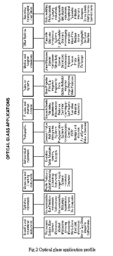
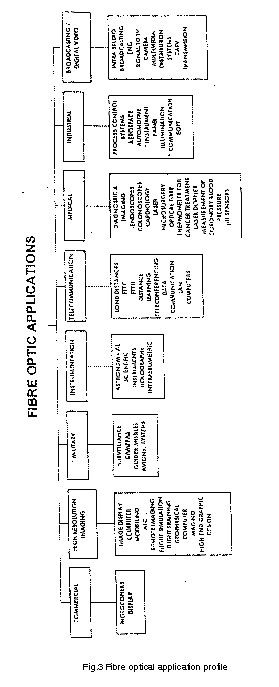
The applications for optical glass and optical fiber have separately been illustrated schematically in fig 2 and 3 respectively.
STRUCTURAL LAMINATE BAG MOLDING PROCESS
INTRODUCTION
Bag molding is one of the oldest and most versatile processes used in the manufacturing of reinforced plastic parts. It is a process for molding rein forced preimpregnated material containing a thermosetting resin. The lamina are laid-up in a mold, covered with a flexible diaphragm and cured with heat and pressures. After the required curing cycle, the materials become an integrated molded part shaped to the desired configuration.
Bag molding is considered to be a "state-of-the-art" process because the skill and "know how" of the workman laying-up and bagging the part determines to a great extent the quality of the finished part. In order for a company to remain a leader in the bag molding phase of reinforced plastics, it must have well trained production personnel and an aggressive reinforced plastics development program. The newest materials that have been successfully bag molded in the aircraft industry are made from boron filaments preimpregnated in an epoxy resin. An airflow deflector door, wing trailing edge panel, and main landing gear at door made of born-epoxy composite are flying on an F-111 aircraft.
The size of a part that can be made by the bag molding process is limited only by the curing equipment, i.e., the size of the curing oven or autoclave.
The process is recommended for the following types of parts: (1) prototype, (2) limited production, (3) production run of complex parts which are not practical to make with matched dies and, (4) extremely large parts.
GENERAL DESCRIPTION OF PROCESSES
The general process of bag molding can be divided into three basic molding methods: pressure bag, vacuum bag, and autoclave as shown in Figure 1.
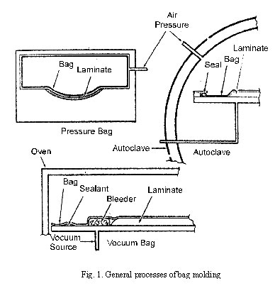
Vacuum bag and autoclave methods are used to produce a majority of bag molded parts. The main advantage of the vacuum bag and autoclave methods are that the tooling is relatively inexpensive and the basic curing equipment (oven and autoclave) can be used for an unlimited variety of shaped parts. The disadvantage of the pressure bag system is that the tooling is relatively expensive because it is combiend with the curing pressure system and can only be used for the specific part for which it was designed. Therefore, this paper will deal primarily with the principles of vacuum bag and autoclave molding which are similar.
THE BAG MOLDING TEAM
The successful bag molding of a reinforced plastic part is dependent upon the coordinated (TEAM) effort from the design to the completed part. The TEAM is composed of members from design, material and processes, tooling, quality control, and production.
Each group is dependent upon the inputs from each of the other groups. For example, the designer must know the properties of the available materials, various types of tooling available, level of the quality control that will be maintained during fabrication , and the general level of production workmanship.
Functions and responsibilities of each individual will be explained in detail which will emphasize the coordinated effort necessary for successful production of bag molded parts.
Designer
Primary responsibility of the designer is to create a part and establish on paper in two dimensions information necessary for: (1) to login to design the necessary tools, (2) quality control to make detailed processing steps and, (3) production to combine this information and tools with the proper materials and with fabrication skill to produce a full size three dimensional part.
The principles that should be used by the designer include:
Drawing a completely described part that can be successfully produced by combining correct materials, bag molding process and good workmanship.
Remembering that reinforced plastics are not metals and parts should be designed to take advantage of the unique properties and processing methods available for reinforced plastic parts.
Providing a simple design that will fulfill the requirements.
Keeping abreast of the newest materials and processes being developed to improve reinforced plastic parts.
The basic sources of information on reinforced plastics available to the designer are:
Engineer's design manual,
Materials manual, and
Surveillance of the fabrication of the parts that he has designed.
Materials and Processes Engineer
The function of this individual is to gather information from available sources, to consolidate and evaluate this information, and to distribute the information as follows:
The design and materials manual to the designer, and
The general processing specification to tolling, quality control and fabrication.
The main sources of current information are: material vendor's literature, technical magazines, governmental agency reports, reinforced plastic society reports and symposia, and in-house testing and developmental programs.
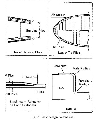
The primary materials used is bag molding are thermosetting resins with fibrous reinforcements. The resin is called the matrix which holds the reinforcements together in the designed configuration. The reinforcement is the major structural components of the part.
Another responsibility of the materials and processing representative is to establish the basic design parameters and general processing specification based upon the bag molding process equipment, tooling and production capability of his particular company.
Typical design parameters that should be established and included in the design manual are:
- Radii
- Draft
- Tie plies and sanding plies
- Surface control
- Steel edge member
- Warp direction
- Transition area
- Steel edge member
Methods of indicating some of these basic design parameters are depicted in figure 2.
Tooling Engineer
The function of the tooling engineer is to provide the necessary tools for production to combine the material, processes and good workmanship into a final part that is defined by the drawing.
Reinforced plastic parts have suffered in the past because of the false economy idea that acceptable bag molded parts can be fabricated on inadequate tools. So many times a tool is incorrect dimentionally or out of contour or fails during the cure cycle. Many times a "single-shot tool" has been pressed in an attempt to make a few parts and the number of required parts has all of a sudden doubled or tipled and the inadequate tool remains in production.
Quality Control Engineer
The primary responsibility of the quality control engineer is to insure the integrity of the materials and fabrication processes during the production of the parts. Each parts must be representative of the parts as described on the engineering drawing. The quality control enginner should:
Perform acceptance tests on all production materials.
Establish individual cure cycles for each group of parts on similar tools making allowance for size, material of tool, heat up rate, etc.
Select and control secondary materials used during the fabrication of parts.
Develop details processing steps for complicated parts in line with the overall general processing specification.
Maintain general inspection and surveillance during the fabrication of parts.
Answer shop processing problems.
Determine causes of defects in parts and provide corrective action.
REINFORCED MOLDING COMPOUNDS
DEFINITION
For purposes of this chapter, reinforced molding compounds will include those two materials which have most commonly been identified in the plastics industry as (1) "premix" [also known as "dough molding compound (DMC)." "flow-mix," or "bulk molding compound (BMC"] and the closely related but slightly different product, (2) "sheet molding compound (SMC)." [also known as "flow-mat" or "mold-mat"] "Premix" and "sheet molding compound (SMC)" are the terms that will be used herein.
Premix has been defined as: "A fiber reinforced other most molding compound not requiring advancement of cure, drying of volatilize, or other processing after mixing to make it ready for use at the molding press. To this might be added, "and which can be molded without reaction by products under only sufficient pressure to flow and compact the materials".
If the word "mixing" in the above is changed to "manufacture" the definition can apply equally to sheet molding compound. The principal differences between premix and SMC are in the manufacturing methods and in the form in which they reach the molder. Each can be formulated of the same basic ingredients.
Premix is formulated by combining all the ingredients in an intensive mixing process. It emerges from the mixer in a fibrous putty form, and it can be used directly, the operator merely weighing out charges. Some formulations can be compacted and extruded into bars or "logs" of simple cross section to facilitate handing. Sheet molding compound, as the name implies, reaches the molder in the form of a thin, semitacky sheet which is cut and plied to suit the article being molded. It is made by impregnating a chopped strand mat with previously blended resin, filler and other ingredients.
Most of our concern in this chapter will be with glass fiber reinforced polyester materials: however, premix can be made with other solvent less resin systems such as epoxies, and with other reinforcing fibers including sisal, asbestos, chopped nylon rag and even wood. On the other hand, sheet molding compounds have not as yet been commercially offered in any but polyester-glass fiber compositions.
HISTORY
Premix
Premix first became a practical possibility when glass fiber rovings came on the market in 1949. Prior to this some reinforced polyester molding compound was made by chopping fiberglass fabric prepreg into small pieces. Inspite of many disadvantages high cost, residual solvents, no internal release agent, no fillers etc. some useful products offering properties available in no other known material were successfully molded.
It is difficult to tract down the first premix compound of the new breed, othe earliest were probably made about 1950, employing a process of impregnating roving strands with the resin, filler, etc. blend, and chopping them to length in the wet stage. Wetting glass fibers with a resin containing much filler is a difficult and slow business, consequently these premixes had a high glass content.
Sometime in the early 1950's the concept of adding prechopped glass fibers to a resin-filler mixture was conceived, and by the mid-1950's premix molidng was a going business. It was, however, delayed in development by the fact that neither the compounders nor the molders were experienced in the kind of business in which they found themselves. No compounders of conventional thermoset compounds were initially interested. As a result such simple things as internal mold release were a long time coming. And no compression molders would contaminate their premises with the sticky, smelly stuff, so their extensive knowledge of mold construction, ejector mechanisms, heating devices, etc. was denied the fledgling industry.
The first move to high volume occurred with the development of a premix based on sisal fibers and the molding of automobile heater housings, the largest (in area) items ever made in volume production from a molding compound up until that time. While this type of compound was no outstanding in its physical properties, the unique character of the sisal fiber permitted intensive mixing without fiber damage and promoted homogeneity throughout a large molding, which was not possible with the glass fibers then available.
While the easy molding, low cost sisal premix continued to dominate the high volume automobile market, the development of a resin coating for glass fiber strands that preserved their integrity; i.e. kept them intact as bundles of fibers through the mixing process, made possible large area molding with strength, chemical resistance, electrical insulation values and other desirable properties. Consequently heavy, large area electrical and chemical items as well as a few commercial products such as internal parts of appliances, where surface quality was a secondary consideration, became commonplace. Surface waviness and coloring problems limited product applications to items and/or parts no normally exposed to the consumer's view.
To obtain water and stain resistance no offered by sisal and glass fiber reinforced compounds, the use of chopped nylon rag was introduced in the early 1960's. This material has brought about high volume manufacture of such items as shower bases with dimensions up to 3 feet ž6 feet and weighing as much as 75 pounds each.
As mentioned earlier, the applications of glass fiber reinforced premix were seriously limited by irregular waviness of the molded surface. Developments in Germany and England about 1960 in the use of chemical thickening agents and thermoplastic additives markedly reduced cure shrinkage, resulting in imporvement in the quality of the surface as well as limitation of other distortions. These improvements unfortunately required some compromises, and efforts to produce a distortion-free premix without sacrifice of other properties continue up to the present.
Other significant stages in the history of premix are : the use of hydrated alumina as an additive to provide either self-extinguishing or non-tracking qualities; the development of fast cure resins; and, very recently, the molding of premixin injection-transfer type "automatic" presses that give promise of putting premix in direct price competition with low cost thermosets and thermoplastics.
Sheet Molding Compound (SMC)
In this process the mat or preform and resin-filler are brought together at the press and the resin is distributed with varying degrees of uniformity throughout the reinforcement by the force exerted as the mold closes. While many techniques have been developed to overcome the inherent disadvantages, this process is messy, difficult to mechanize, and requires substantial operator skill.
The obvious simplification of recombining the resin and mat, so successful with prepreg woven fabrics, defied solution. For most convenient use the sheet of material must be dry in the uncured state. Mats with sufficient insoluble binder to permit impregnation by the conventional re-insolvent system and subsequent passes through a drying tower do not make compounds that flow properly in the molding process. The development of the chemical thickening process mentioned earlier provided a solvent less low viscosity resin system that permits impregnation of mats having a minimum of soluble binder. The resin, wet in the initial stage, readily impregnates the mat. In time (3 to 48 hours) it converts to a dry or slightly tacky state, without further processing, other than rolling up in a polyethylene separating film. While sheet molding compound has not replaced conventional mat and preform molding in products with demanding mechanical properties, nor has it particularly lent itself to a high order of mechanization, nevertheless it has found a place in the market between the areas served by premix and preform.
PROPERTIES
Premix and SMC offer an extraordinary range of desirable properties. The nealry infinite variability of resin, filler, and reinforcement types and contents would seem to permit "tailoring" a compound for any design or performance requirement. Within limitations this is true, and it is probably the single most outstanding quality of these materials.
It also makes definition of detailed properties difficult. However, the important attainable characterisitcs, if the compound is properly formulated are:
- Excellent electrical performance-especially resistant to tracking.
- High strength-particulary impact strength.
- Heat and flame resistance.
- Dimensional stability.
- Chemical resistance.
- Rapid cure.
- Low molding shrinkage.
- Low molding pressure.
- Thick, thin, and variable thicknesses are moldable.
- Low cost.
Electrical. An important electrical property is the ability to resist arcing. This is combination with strength, heat resistance, dimensional stability, moldability, and reasonable cost has resulted in widespread use of these plastics in high voltage application s. The arc suppression qualities come largely from the inclusion of such inert inorganic filler materials as hydrated alumina, silica and china clay. Additions of small amounts of fine powdered polyethylene (of the order of 5 percent by weight) and the use of nylon fiber are reliably reported to improve arc resistance. For maximum arc resistance it is necessary to minimize both the resin and the glass fiber content, with resultant reduction in mechanical properties.
Table 1 shows some relationships among resin, glass fiber and filler contents with respect to arc resistance.
Table 1 Arc Resistance as Affected by Formulation.
| Arc. Resistance Sec. ASTM D-495 |
Glass Filler% |
Filler% |
Resin% |
Filler |
| 202 |
15 |
64 |
21 |
Hydrated Alumina |
| 240 |
9 |
73 |
18 |
" |
| 264 |
7.5 |
75 |
17.5 |
" |
| 300 |
0 |
85 |
15 |
" |
Strength. The strength and stiffness that distinguish reinforced molding compounds obvioulsy are due to the proportion of reinforcing fiber used, which is not to say that the other ingredients do nto influence the mechanical properties. In premix compounds fiber lengths in excess of inch produce little if any practical increase in molded properties, and lengths over " inch create mixing and molding problems. A typical relationship is shown in Figure 1.
No published data are available on the effect of variable fiber lengths in sheet molding compounds. While most are made form chopped strand mat having a nominal fiber length of 2 inches it is unlikely that this is the optimum length for all purposes.
The mechanical properties increase with higher reinforcement content, again not proportionately and not without detrimental side effects. Table shows some typical relationship.
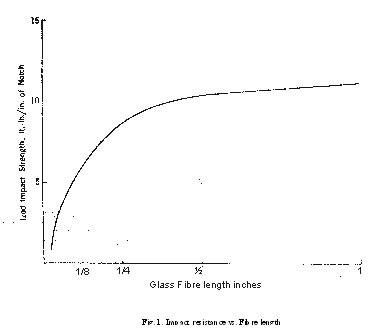
Heat Resistance-Flammability. Heat resistance, short term hot strength and flammability tend to be considered together but they are not necessarily common properties of a given molding compounmd. "Heat resistance" relates to the long term resistance to thermal degradation below the flammability temperature. "Short term hot strength" or simply" hot strength" pertains to the thermoplasticity qualities of the resin. Heat resistance and hot strength are properties derived largely from the resin, although there is evidence that certain fillers do enhance heat resistance, even though the mechanism is not explained. Flammability is of course the measure of overt burning. Inspite of the fact that all organic materials will burn (if heat above the ignition temperature continues to be applied) compounds are variously called "non burning," "self-extinguishing" and "fire retardant" depending on their ease of ignition, ability to extinguish when the heat source is removed, and their rate of burning. Flame resistance in polyester resin is achieved with halogenated resins (plus antimony trioxide for maximum effect) adding halogen- and phosphorous-containing compounds to conventional resins, and by using hydrated alumina as the principal or sole filler in a compound. Table 3 provides some data on flame resistance of various polyester premix formulations.
Table 2. Mechanical Properties vs Fibre Content in Flowmix
| Glass Fiber Content % 1/2 in fibers |
Izod impact ft-lb/in Notch |
Flextural Strength psi |
Flexural Modulus psiÃ-10 |
Tensite strength psi |
Approx Cost/L.b |
| 10 |
3.66 |
9800 |
1.53 |
3550 |
.12 |
| 20 |
6.13 |
16000 |
1.64 |
6340 |
.15 |
| 30 |
7.37 |
19600 |
1.66 |
7920 |
.18 |
| 40 |
10.65 |
22300 |
1.72 |
9530 |
.21 |
| 50 |
11.03 |
23200 |
1.59 |
6890 |
.24 |
Table 3. Flame Resistance of Aluminum Hydrate vs Halogen Antimony Trioxide Systems in Premix Formulations.
| Formulations |
|
|
|
|
|
| "Plaskon" 9520 resin |
30 |
30 |
None |
None |
30 |
| Halogenated resin (28"CI) |
None |
None |
34 |
34 |
None |
| Benzoyl peroxide paste |
0.6 |
0.6 |
0.6 |
0.6 |
0.6 |
| Aluminum hydrate (Hydral-710) |
53 |
38 |
None |
15 |
None |
| Clay ASP-400 |
None |
15 |
44 |
29 |
53 |
| Antimony trioxide |
None |
None |
5 |
5 |
None |
| 1/4 in fiber glass |
15 |
15 |
15 |
15 |
15 |
| Zinc stearate |
1.4 |
1.4 |
1.4 |
1.4 |
1.4 |
| Flame Resistance |
|
|
|
|
|
| By ASTM-D-635 |
N.B |
N.B |
N.B |
N.B |
S.E |
| By Federal spec meth 2023 |
|
|
|
|
|
| Ignition time, see |
154 |
135 |
95 |
150 |
93 |
| Burning time, sec |
31 |
60 |
56 |
27 |
234 |
Phenolic resins are inherently flame resistant. Halogen and phosphorous compounds, as well as the use of chlorendic anhydride (50 percent or more) as a hardener, will provide a measure of flame resistance to epoxies.
Stability. The dimensional stability of premix and SMC formulated with polyester resin, glass fiber reinforcement and china clay, silica, alumina and some other fillers is unexcelled. Post molding shrinkage is nonexistent water absorption is very low, resulting is very slight changes in weight and not easily detected dimentional changes. The thermal expansion coefficient is very near that of aluminum, sometimes lower. Changes with continuous exposure to elevated temperature can be minimal. Figure 2 shows some stability characterisitcs of a premix compound formulated with a general purpose polyester resin.
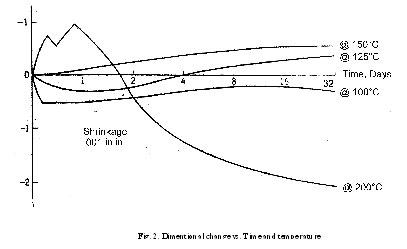
Corrosion Resistance. The chemical or corrosion resistance of these compounds can generally be rated excellent. By selection of resin and filler a compound to resist a specific exposure can usually be formulated. The properties of the resin chosen are all important. No filler or reinforcement will compensate for the failings of the resin. Acid and alkali resistant polyesters and acid resistant epoxies can be used in premix. There are at present limitations on resin selection for sheet molding compounds since the resin must also respond to the chemical thickening mechanism. Of the common fillers, china clay and silica are good all around, calcium carbonate has good alkali resistance but is poor in acids. Better performance might be expected from so-called corrosion resistant glass fibers, but no evidence supports this.
Cure Rate. Rapid to very rapid cures at temperataures below that for other thermosets are possible with polyester-based compounds. With some special polyesters and/or more or less conventional ones crosslinked with ortho-mono-chlorostyrene, cure times of about 18 seconds are possible at 300øF in parts about 0.1 inch thick. The exothermic nature of polyester curing results in an imbalance of cure rate to thickness such that thick sections cure is shorter times than might be expected. Also many parts that are nominally thin but have thick ribs or bosses can be removed from the mold at an early stage and the cure will continue to completion in the interior of the thick sections. Standard polyester premix and sheet molding compounds require 45-60 seconds at 280-300 for a 0.1" thickness made for prompt use (within two or three days) can be formulated to cure rapidly and effectively at temperatures as low as 225øF.
Shrinkage. Glass reinforced compounds can be expected to have very low molding shrinkage. A maximum of 0.004 inch per inch is typical, with many compounds down nearer 0.001 inch per inch. The glass fibers and inorganic fillers that have little thermal shrinkage contribute most to the low overall mold shrinkage. However, the combination of low shrink, high strength fibers with the high cure and thermal shrinkage of conventional resin systems develops considerable stress in the resin matrix between the fibers. The secondary effects of the stress are surface waviness, warping, surface cracks and internal voids. Some of these faults can be reduced (at a great sacrifice of various properties) by the use of organic fiber reinforcement which shrinks to match the resin or by the use of short or filamentized glass fibers that contribute little strength.
It is fortunate for the future of the reihforced molding business that some ways to counteract the resin shrinkage have been found, and these are described below. The chemical thicknening process used in making SMC and some premix compounds reduces both cure shrinkage and orientation and disassociation of the fibers as the charge flows to fill the mold, with consequent reduction of the above-mentioned faults.
The addition of 5 percent by weight of fine powdered low density polyethylene (less than 30 micron particle diameter) to either standard or chemically thickened systems further reduced shrinkage induced faults.
Another solution to the resin shrinkage problem involves the use of a liquid acrylic monomer (in addition to styrene). The mechanism is not as yet fully explained. The acrylic monomer does not react with the polyester but homopolymerizes during the expotherm of the polyester reaction, leaving foamlike occusions which apparently exert some pressure in their formation to resist the polyester polymerization shrinkage.
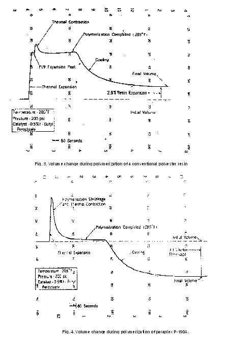
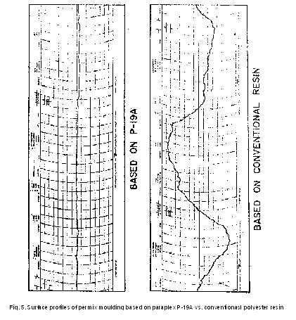
The most obvious advantages of the low shrinkage resin systems appear in the surface smoothness. This is apparent in Figure 5 which compares by Microcorder readings the surface waviness in premix compounds based on low shrink and onverntional resins. The other common faults are similarly influenced.
While there are claims of equal or superior properties for the low shrink systems there are so many different conditions for which a reinforced compound may be specially formulated that time has not permitted all-encompassing evaluations. It is true that mechanical, electrical, and chemical properties adequate for a wide variety of applications can be attained with low shrink compounds, and that products made with these materials can be painted with a minimum of surface preparation.
Molding Pressures. Low molding pressure is a big advantage of premix and SMC. The highest pressure required is at the low end of the pressure needed for typical phenolic, melamine, and urea compounds. The requirements are no more than those necessary to flow the material to the extremities of the mold. None is needed to keep reaction by-products such as water or residual solvents from gassing and forming blisters or voids, Premix compounds can be formulated to mold simple shapes at 100 psi. Chemical thickened compounds require higher pressures in the range of 500 to 1500 psi, and some recommendations for sheet molding compounds go up to 3000 psi. These low pressure requirements permit the use of molds and presses that cost less than those for any other molding material.
Thickness. Wide variations in thickenss are possible within the same molding without major detrimental efffects if proper care is taken in desin of the transition from one thicknerss to another. With conventional premix compounds, sinks or depressions (often with small cracks) will appear opposite stiffening ribs in thin flat sections unless generous blend radii are provided.
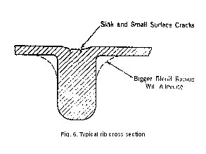
Other faults that occur with thick and thin sections have much to do with fiber orientation. The fibers tend to align themselves with the direction of flow in thin sections and crosswise from thin into thick sections. The results, if not appearance defects, are often wise and unexpected variations in strength. Chemical thickening and the use of flow controlling fillers help to keep the fibers in their original heterogeneous relationship.
Cost. Even though glass fibers and some of the other ingredients of reinforced molding compounds are relatively high in cost, the capacity to employ large quantities of low cost fillers and still maintain excellent properties puts these materials at the low end of the cost-performance scale. Table 2 lists some material costs for chemically thickened premix of various glass contents. To this must be added mixing costs which can be widely variable depending on the quantity processed: I cent per pound is possiable in a moderate sized operation. Compounds with sisal or chopped nylon rag reinforcement can have even lower raw material costs plus the advantage of lower density.
Sheet molding compounds made directly from glass fiber roving can have a raw material cost of 20 cents/pound with 30 percent glass fiber content or about 25 cents/pound if made from glass fiber mat. The conversion to a usable molding compound is more costly than for premix at present, possibly as much as 10 cents/pound, in part because refinement of techniques and machinery is far from complete.
APPLICATIONS
The great variability in attainable properties of reinforced molding compounds has resulted in a wide range of applciations in which generally the only common characteristic is that they are structural products i.e. they repalced or were used in place of wood, metal, ceramics, or laminated reinforced plastics. In addition to the basic structural quality they can be specifically formulated to attain low cost, corrosion resistance. Heat resistnace, good electrical properties, flame resistance, etc. Reinforced molding compounds can be and have been applied successfully in place of such diverse materials as concrete, paper mache, wood, sheet steel, other plastics, aluminium, zinc, iron and bronze castings, etc. in almost every instance offering lower cost as well as some important improvement in the performance of the product.
Until the fairly recent development of low shrink, low profile formulations most applications were industrial-technical products or consumer products not normally exposed to the user's view. While there are not many applications to be cited as yet where the product is decorative as well as functional in a structural or engineering sense, the designer can now feel free to consider these materials as both.
Some representative successful applications are described below to illustrate what reinforced molding compounds are good for and where they should be used. Where possible, the alternate material will be indicated with the justification and/or advantages of the reinforced molding compound.
The sheer volume of material consumed makes the automotive applications of prime interest. Components of the heating and ventilating system, and parts such as hoods on limited production models have constituted an estimated one-third of the total reinforced plastics production.
Automobile heater housings and related during molded of sisal reinforced polyester premix are used in nearly every make of car. They replace an assembly of many pieces of sheet metal and fiberboard with a product offering simpler installation, better performance (less noisy, smoother interior surfaces with better air flow), no necessity for painting, and low cost. Some competition might be expected from thermoplastics, but the low cost ones fall short on performance and the high performance types fail on the cost criterion.
A standard on many station wagons, the simulated wood train, is a glass reinforced extruded polyester premix molded with a wood grain printed paper overlay. The appearance is substantially the same as natural wood, the cost is much lower, and the part does not check and crack on weathering.
Some recent applications have included parts that are painted to match the exterior of the car. This calls for a material that is about as smooth as sheet metal and can withstand the temperatures of the paint baking oven. In the past most such parts have been zinc die castings, with some limited use of high performance thermoplastics. The low shrink, low profile resin systems offer surfaces nearly equal to sheet metal, better heat resistance than the thermoplastics and lower cost than zinc die castings or heat resistance thermoplastics.
Electrical and electromechanical products are somewhat "behind the scene" applications where reinforced compounds have made a genuine technical and economic contribution. So-called electrical "switchgear" housings, formerly fabricated from flat plastics laminates in a metal framework, can now be molded of premix or SMC with advantages of lower cost, better electrical performance, and considerably decreased dimensions. The elimination of metal structure and the excellent arc resistance of the reinforced molidng reduces the clearances needed to prevent arcing under high voltage conditions.
Outdoor applications have been few since the weathering characteristics of reinforced compounds have not been outstanding. Recent improvements in compounds and coatings have resulted in some applications for use as medium voltage (up to 34 kv) insulator brackets for above ground power distribution lines.
Dimensional stability, non-conductivity, precision location of holes and other parts as molded, combined with initial low cost made this part an attractive replacement for die cast aluminum formerly used.
Appliances. The advantages include corrosion resistance and good physical strengths. In both cases the blower or fan motor is mounted directly on the part which aids in reducing the noise level. A measure of thermal insulation is also achieved. Economies, again, were realized in eliminating the need for painting and by the elimination of sub-assembling a center partition, a blower scroll, a control mounting housing and all the mounting brackets. Tooling costs were less than would be required for the many sheet metal parts required to make up a metal assembly.
MATERIALS
Since the basic materials are rather completely described in other chapters, the discussion in this chapter will be limited to material requirements and qualities that are specific to premix and sheet molding compounds. A typical compound contains resin, reinforcment, filler, release agent, colorant and curing agent.
The resin should ideally have a low viscosity to permit easy mixing, but high enough not to liquify and separate from the other ingredients as the compound flows in the mold. It should cure rapidly, have high hot strength to permit removal of the part form the mold without damage, and bee sufficiently resilient to permit some deformation of the part without cracking.
Most polyester resins for reinforced molding compounds are in the 25 poise viscosity range although resins from 10 to 2500 poises are being used. Up to 600 poises can be mixed in conventional equipment without viscosity reducing solvents that msut be evaporated. Polyester resins are often classified for molding compound purposes by : (1) their basic polymer ingredient for inntance, orthophthalic, isophthalic, bisphenol or "Het" anhydride: or (2) their crosslinking monomer-styrene, vinyl toluene, DAP, monochloro-styrene, etc. Generally the lowest cost is an orthophthalic based polymer with styrene monomer. Isophthalic, bisphenol and "Het" anhydrides offer better mechanical properties, corrosion resistance and reduced flmmability respectively. Vinyl toluene is less volatile than styrene and compounds made with it do not suffer from monomer evaporation on exposure to air. DAP is even less volatile and provide better electrical properties as well. Mono-chloro-styrene, just out of the development stage and more expensive, provides very rapid cures-one-fourth that of more conventional systems-and other desirable properties. See figure 7.
In addition there are resins especially formulated for chemical thickening purposes and other low shrink devices as mentioned in the earlier section on properties. Some typical properties of polyester resin-monomer system are shown in Table 4.
Table 4. Polyester molding compound resins-properties of unfilled castings
| |
1 |
2 |
3 |
4 |
5 |
6 |
| Polymer Monomer |
Isophthalic Mono-chiorostyrene |
Ortho Styrene |
Iso Styrene |
Iso Viny Toluene |
Orthe Styrene |
Orthe DAP |
| Vicosity-poises |
25 |
26 |
27 |
26 |
24 |
400 |
| Specific gravity |
1.20 |
1.22 |
1.20 |
1.09 |
1.17 |
1.26 |
| Heat distortion (temp) |
109ºC |
72ºC |
80ºC |
101ºC |
74ºC |
200ºC |
| Flexural strength, psi |
17.4(a) |
17.500 |
17.600 |
18.500 |
23.000 |
12.000 |
| Flexural modulus. psi |
56Ã-10 |
56Ã-10 |
42Ã-10 |
55Ã-10 |
50Ã-10 |
45Ã-10 |
| Tensile strength. psi |
|
8900 |
9500 |
7730 |
13000 |
... |
| Tensile elongation |
|
1.8ø |
6.5ø |
2.9ø |
4.0ø |
1.5ø |
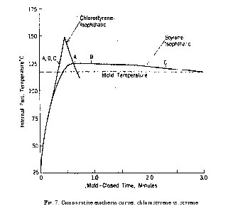
Reinforcements
Reinforcements for premix include glass, asbestos, sisal and various other organic fibers. The glass fibers used are of three tyeps: chopped strand (bundles of continuous filaments); chopped spun roving (short fibers made into threads); and a resin-coated chopped strand identified generally as "high strand integrity" fiber (or HSI). They are available in various lengths with 1/4 and 1`/2 inch most commonly used. The HSI fiber resists degradation in the mixing process (i.e., the strand does not break up into its individual filaments) and provides the best overall mechanical properties, especially in parts requiring long flow. Other glass fiber forms have better color characteristics and incidental other properties. While glass fibers generally give the maximum mechanical properties, sisal fibers make an easy flowing compound, excellent for large moderately complex parts not requiring a high degree of water resistance, and can be used in combination with glass fibers. Asbestos fibers are used where special chemical resistance is sought. A very low cost molding with excellent water and stain resistance plus good electrical properties can be made with diced nylon tricol fabric. The mold shrinkage is quite high but since there is no differential between the nylon and the resin the surfaces are remarkably smooth. The color and weave of the nylon fabric are difficult to mask and the mechanical properties of such moldings are low. The lower molded density permits thicker sections which can sometimes compensate for the lower strength.
Sheet molding compounds are commonly reinforced with a soluble binder chopped strand mat having a fiber length of about 2 inches. Recent developments in compounding SMC are leading to direct deposition of chopped glass fibers into a resin-filler matrix instead of impregnation of a pre-manufactured mat. These fibers can be of any length up to 2 inches, with shorter length (1/2 inch, 1 inch) offering better moldability in complex shapes without much loss of mechanical properties. For higher strengths the HSI type fiber is best although a smoother surface results from use of the softer finish spray up fiber.
Fillers
The fillers in common use are in four chemical groups: silicas and silicates, carbonates, sulfates, and oxides. However, almost any material that can be reduced to a particle size in the range of 1.2 to 50 microns can be used. The first group includes asbestos, tale, china clay (kaolin), silica (sand), diatomaceous earth and volcanic ash: the third includes barium sulfate (barytes) and calcium sulfate; and the fourth hydrated alumina. In those groups are the so called natural materials that are brought to a useful state by grinding (wet) and/or dry and those produced by chemical precipitation. The latter can be of the smallest available particle size as well as the most uniform (almost constant), which may be of questionable advantage as well be pointed out later. The specific gravity ranges from 2 for diatomaceous earth to 4.45 for barytes, with the predominately used materials (china clays and calcium carbonates) in the 2.6 2.7 range. Price ranges from 1 to 4 cents per pound in carloads, with the clays and clays and calcium carbonates in the 1 to 2 1/2 cents category. Various other detailed characteristics and properties of fillers will be discussed below.
Particle Size: These materials are commonly classified as to particle size in terms of the fineness of sieve through which a given percentage will pass; for examaple, 99.8 percent through a 325 mesh screen, or by the particle size expressed in microns. For our purposes the figure in the example is a reasonable low limit. The space between the wires of a 325 mesh is 44 microns and any substantial quantity of larger particles is not satisfactory.
Particle Size Distribution. The particle size classification above provides information as to the maximum particle size but nothing as to the smallest or to the quantities of various sizes in between. Fortunately this information is available for most of the fillers in the form of a particle size distribution graph. It is reasoned and has been shown by experience that a filler with a fairly wide particle size range such that the smaller particles fit between the medium, the medium between the larger, etc. will provide a compact arrangement requiring a minimum of resin to fill the space between the particles. The greatest economy as well as the best mechanical properties result, when there is sufficient resin to fill the spaces and not so much that it separates the particles. Other necessary characteristics of a molding resin complex may limit attainment of this optimum condition.
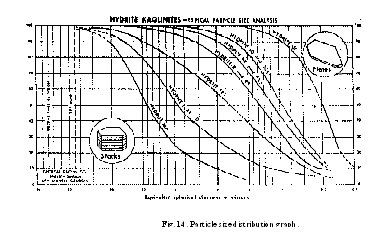
Oil Absorption. This property, which is stated as the percentage of linseed oil required to wet out a given weight of filler, provides, when selecting fillers, an approximation of the relative amounts that could be used to attain the same viscosity. The oil absorption is a function of the specific surface of the particles. Porous particles have higher values than nonporous of the same size. The lowest oil absorption permits the highest proportion of filler, and in most cases the principal filler in a resin-filler system can be one of low oil absorption value.
Thixotropy. Thixotropy is a phenomenon in which the nominal viscosity of a material is markedly reduced when the material is distributed, returning to the original state when the disturbance ceases. Some high oil absorption fillers, while providing high viscosity, also have a substantial thixotropic effect. Mold closing forces are usually sufficiently disturbing that viscous thixotropic resin-filler systems can exhbit the flow properties of lower viscosity nonthixotropic systems.
The bulking fillers are principally clays and calcium carbonates. Calcium carbonates have the lowest oil absorption and consequently more can be put into a mix; however, their characteristics are such as to give poor flow. Clay filled compounds have better flow and molded properties are better in many respects, but not color. Frequently a combination of clays and calcium carbonates provides a high filler loading with good flow. Addition of smaller quantities of high oil absorption talc to predominately calcium carbonate filled compounds will also impove the flow with less effect on the good color. Asbestos also aids flow but is bad in color.
The following list of desirable filler properties can be used to narrow down the tremendous number of minerals offered for use in reinforced plastics:
- Low specific gravity
- Low oil absorption
- Nonporous
- Nonabrasive
- Low cost
- Readily dispersible without agglomeration
- Chemically pure and white
Wide particle size range-about 1 to 15 microns with a mean diameter of 5 microns.
There are also additives for special use that may come under the heading of fillers. These are materials for fire resistance, which as antimony trioxide used in conjunction with halogen containing resins or additives; for chemical thick, which include magnesium oxide and calcium hydroxide; and for lowering shrinkage effects, such as fine powdered polyethylene.
Release Agents
Internal mold release is used in all compounds. Zinc stearate is most common . Also used are calcium and aluminum stearate and stearic acid for lower temperature molding, and an alkyl phosphate product of Dupont, "Zelec UN." The latter is a liquid, is easy to measure, and easy to mix. The stearates are dusty powders.
Colorants
Dispersions of pigments in compatible resins are widely used, but economies can sometimes be effected with the use of lower cost dry color pigments in premixes. The intensive mixing required to amek premix is often sufficient to belnd in many dry pigments properly. Some pigments have an accelerating or inhibiting effect on resins and some consideration should be given to the affects on storage stability and cure time when choosing pigment types.
Curing Agents and Inhibitors
Benzoyl peroxide is a good, economical curing agent for polyesters if long term storage stability is not a factor. It permits molding over a wide range of temperatures. Tertiary butyl perbenzoate requires higher molding temperatures but is very stable and permits higher temperature mixing. Dicumyl peroxide requires a high curing temperature but is also stable in mixing and storage. A new general group of so-called difunctional peroxides (2 available oxygens per molecule) offer what is simply described as a better cure. The molding surface is improved and mold sticking is reduced. The higher temperature most stable versions are in a free flowing powder form most easily identified by their trade names as "Luperox 118" or "USP 711. Reacting at a lower temperature are liquids of slightly different chemistry identified as "USP 245" or "Lupersol 256". The liquids are easy to measure and provide effective cures at temperatures as low as 240øF. The difunctional peroxides are more expensive but they can be used in much lower concentrations and seemingly provide better results to offset their higher cost.
Inhibitors beyond those normally present to stabilized the resin can be used to further promote storage stability of the compound, to prevent gelation during mixing, and, rarely, to control the cure rate. Quinone, hydroquinone and a long list of quinone compounds stabilize without much affect on the high temperataure cure rate. Very small quantities are used in the range of 0.02 to 0.05 percent.
FORMULATION
Formulation is the design of compound to bring about the desired properties in the finished molding within the limitations of the molding conditions. Compounds may be formulated to provide strength, stiffness, toughness, electrical insulation, corrosion resistance, fire resistance, etc. and of the combinations of two or more of these qualities, but first and foremost they must be moladable.
Moldability has been generally defined earlier in this chapter. In addition, a reinforced compound must, to the maximum degree, remain homogeneous as it flow through and to extremities of the mold; i.e. the resin-filler-reinforcement should not separate or serious variations in properties will occur throughout the molding and much of the usefulness of the reinforcement will be lost.
The ideal compound should also flow easily and fill extremities and details of the mold. These two molding characterisitcs are seldom easy to combine with the other necessary requirements and usually the best formulation is a compromise.
The flow properties are a function of the degree to which the resin is absorbed by, or adsorbed, on the filler and reinforcment. Each of the dry ingredients employed in compounds has its own particular resin absorption, or drying effect on the resin. For example, in the case of two very common fillers, china clay has more othan twice the absorptive power of calcium carbonate. Longer glass fibers are less drying, and coated fibers (HSI types) less than conventional. And the dryer the compound the lower the plasticity or flow. Unfortunately for the formulator the resin absorption qualities of the vairous ingredients are not fully determined or published. Some guidance on fillers is available from the linseed oil absorption data published for the paint industry. Table 5 lists oil absorption properties of some commonly used fillers.
Table : Oil Absorption of Some Fillers Used in Reinforced Molding Compounds.
| Filler |
Particle Size Microns |
Specific Gravity |
Oil Absorption |
Cost e/Lb |
| Antimony trioxide |
44 |
5.70 |
11 |
28 |
| Asbestos |
50 |
2.56 |
38 |
2 1/2 |
| Barytes |
7.5 |
4.40 |
11 |
3 |
| Calcium carbonate |
2.5 |
2.71 |
14.16 |
2 |
| Calcium carbonate |
5 |
2.71 |
9.10 |
1 1/2 |
| Calcium carbonate |
7.5 |
271 |
5.5-6.5 |
1 1/2 |
| Calcium carbonate |
14 |
2.71 |
5.6 |
1 1/2 |
| Georgia kaolin (China clay) |
1 |
2.58 |
60 |
1 |
| Georgia kaolin (China clay) |
5 |
2.58 |
32 |
1 1/2 |
| Diatomaceous earth |
7 |
2.05 |
88 |
3 |
| Talc |
5 |
2.71 |
55-59 |
4 |
Not only do the fillers vary in resin absorption but resins vary in their ability to wet the fillers depending on their viscosity, basic chemical construction, type and quantity of monomer, etc.
The answer to the problem of formulating a compound that will have satisfactory flow and maintain reasonable homogeneity lies mostly in the selection of the resin and filler combinations. A high viscosity resin will carry reinforcement and filler well but high viscosity makes mixing more difficult. Combinations of smaller amounts of high absorption fillers, such as china clay and asbestos, with low absorption ones such as calcium carbonate or silica works fairly well to solve both the flow and homogeneity problems.
The chemical thickening process used to make SMC can also be used as a flow control devide in making premix. A resin with a low initial viscosity readily permits addition of large quantities of filler or reinforcement. The thickening effect subsequent to mixing simulates the effect of a high viscosity resin, or the use of high absorption fillers.
Ingredients
Resins. Resin content may range from approximately 18 to 50 percent byweight with a level of 30 percent- a good starting point for almost any compound requirements. Where very low absorption fillers such as calcium carbonates can be used, a resin content at the low level willmake a moldable compound. Where the special properties of a particular high absorption filler suah as asbestos are needed, the resin requirement will be on the high side of the range.
Filler. The filler content of a given compound is indirectly proportional to the amount of reinforcement needed to satisfy the mechanical property requirements. Usually fillers can repalce the reinforcment with minimal effect on the general moladability of the compound. Reinforcement. Glass fiber contents in premix compounds may vary from as little as 5 to over 50 percent. Less than 5 percent provides no detectable structural advantages, and more than 50 percent creates molding problems. Up to 20 percent provides compounds that can be extruded or compacted for easy handling. Higher glass fiber content makes fluffy, springy compounds that do not hang together well, or if they are high in resin content they are very wet and sticky. Sisal fiber can be practically used up to about 20 percent, with as little as 5 percent offering worthwhile reinforcing effect. Upto 10 percent handles well. Nylon tricot fabric chopped or diced can be used up to approximately 15 percent by weight. It makes a light fluffy mix that is difficult to compact and is most easily handled with a deep tray.
Pigments. Concentrations vary widely depending on the depth of color required and it is difficult to indicate a realistic maximum or the point at which some pigments start becoming fillers.
Internal Mold Release. The stearates, aluminum, calcium and zinc are used at the 1-3 percent level, stearic acid about the same. "Zelec UN" is effective at 0.5-1 percent. Some reduction in properties may be expected with excessive use of internal mold release so its quantity should be minimized.
Curing Agent. The catalyst concentration is in proportion to the amount of resin and is usually specified as a percentage of the resin content. Average concentrations for common polyester curing agents are shown in Table 6. Smaller or larger concentrations can be used depending on shelf life requirements, curing temperature and acceptable molding cycles.
Some typical formulations for different purposes are listed in Table 7.
Table : Typical Concentrations of Peroxide Curing Agents
| Peroxide |
Temp. Range.ºF |
% to Resin |
| Benzoyl peroxide |
225-300 |
.5-1 |
| Tertiary butyl perbemzoate |
250-300 |
.5-1 |
| Dicumyl peroxide |
275-300 |
.5-1 |
| "USP 245" or "Lucidol 256" |
225-270 |
.25-.5 |
| "USP 711" or "Luperox 118" |
275-325 |
.25-.5 |
COMPOUNDING
While much of the compounding practice, procedure and equipment is common to both premix and SMC, there are sufficient differences to consider them separately.
